Ratchet mechanism

Inactive Publication Date: 2009-11-12
HORIZON GLOBAL AMERICAS INC
View PDF24 Cites 25 Cited by
  • Summary
  • Abstract
  • Description
  • Claims
  • Application Information

AI Technical Summary

Benefits of technology

[0056]As shown in FIGS. 12A and 17, the mechanism 10 may be freely positioned anywhere along the length of the strap 35. This allows, for example, the mechanism 10 to be positioned in a more comfortable ratcheting position, or away from cargo or surfaces that the user does not want to contact with the mechanism 10. Moving the securing mechanism 10 away from the cargo may prevent the cargo from being scratched by the mechanism 10.
[0057]FIG. 12B illustrates the mechanism 10 folded into a closed position. When the mechanism 10 is folded closed, the mechanism 10 is prepared to either tighten via a standard ratcheting motion, as shown in FIG. 12D, or by using the quick-tightening features 105, as shown in FIG. 12C. In addition, once in the closed position the spool 20 may gather the strap 35 into a substantially Z-fold configuration. The Z-fold configuration may prevent the mechanism 10 fro

Problems solved by technology

Such cargo tighteners suffer from a variety of deficiencies.
Therefore, the tightener cannot be positioned, for example, to avoid contact with the cargo or vehicle.
In addition, cargo tighteners often require two separate s

Method used


Image

  • Ratchet mechanism
  • Ratchet mechanism
  • Ratchet mechanism

Examples


Example

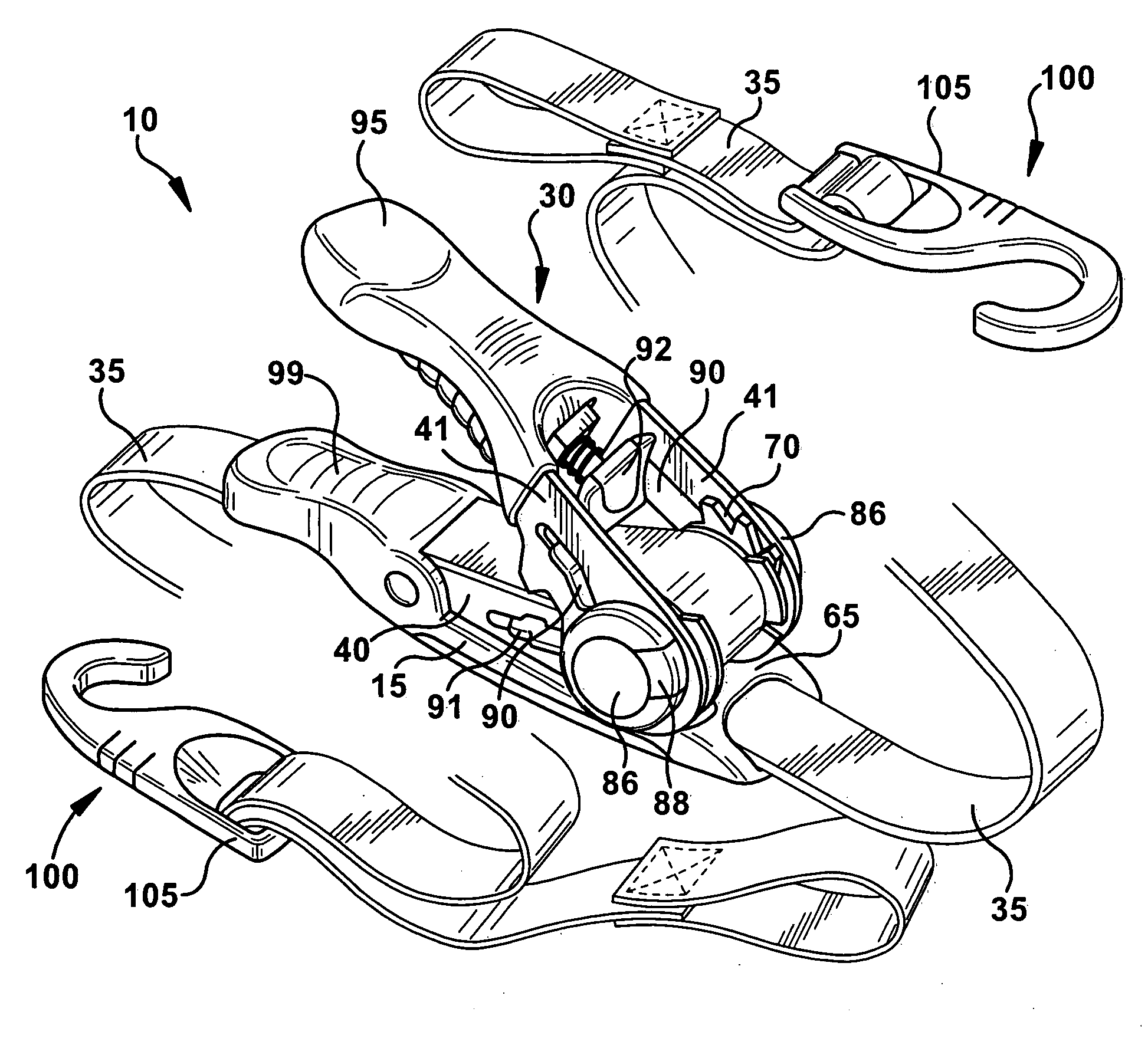
[0031]FIGS. 1-18 illustrate embodiments of securing mechanism 10 (“mechanism 10”). The mechanism 10 may combine the function and benefits of a typical ratchet mechanism into an improved securing mechanism that only utilizes one strap 35, thereby eliminating the need for extra components, which results in cost savings while also speeding up the time it takes to secure a load or cargo.

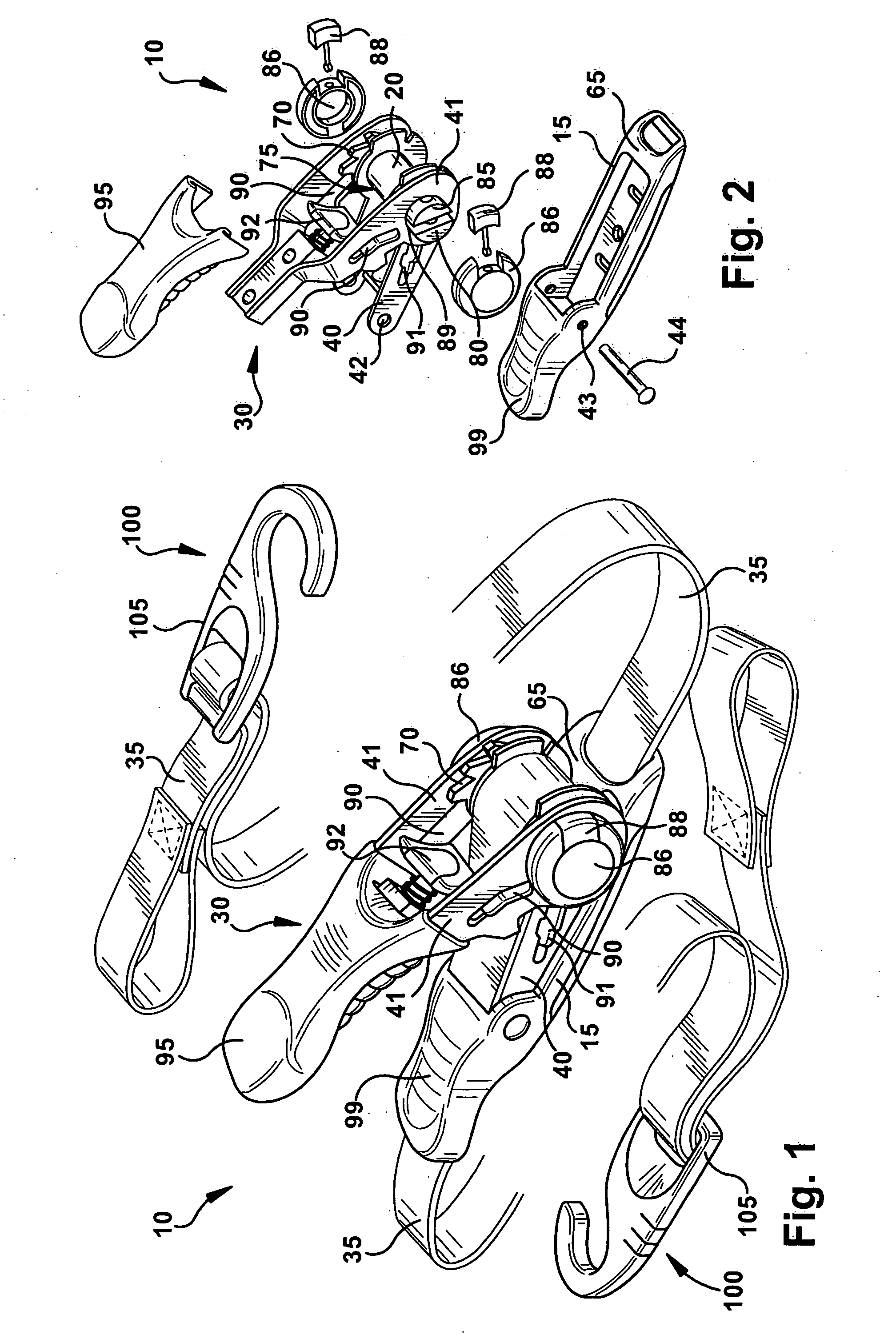
[0032]As shown in FIGS. 1 and 2, the mechanism 10 may include a body 15, a spool hub 20 (“spool 20”), and a lever 30. The mechanism 10 may be selectively positionable along a length of a strap 35. In addition, the mechanism 10 may be capable of bi-directionally gathering the strap 35 about the spool 20 to secure an item or cargo. The body 15 may also include a cap or handle 99 and a strap guide 65. The cap or handle 99 may aid in the securing or ratcheting process. The strap guide 65 may aid in guiding the strap 35 into the ratchet mechanism and onto the spool 20.

[0033]As shown in FIG. 1, the body 15 may...


PUM

PropertyMeasurementUnit
Lengthaaaaaaaaaa

Abstract

A securing mechanism for securing cargo that may include a body, a ratchet, a lever and a release mechanism. The body may be capable of receiving a strap therethrough, wherein the strap may includes opposing ends. The ratchet may include a pair of opposing arms connected to the body and a spool rotatably connected to the arms. The spool may include a slot to receive the strap into a z-fold configuration. The lever may be rotatably attached to the arms and reciprocated between an open position and a closed position, wherein the lever may include at least one pawl to engage the ratchet wheels and may rotate the spool when the lever is reciprocated. The release mechanism may be capable of selectively disengaging the pawl from the ratchet wheel. The securing mechanism may be selectively positionable along the strap when the strap is bi-directionally gathered onto the spool.

Description

CROSS-REFERENCE TO RELATED APPLICATIONS[0001]This application claims benefit from U.S. Provisional Patent Application No. 61 / 072,141, entitled “Ratchet Mechanism,” filed on Mar. 28, 2008, which is hereby incorporated in its entirety by reference.FIELD OF THE INVENTION[0002]The present invention relates generally to a securing mechanism, and more specifically, to a bi-directional ratchet mechanism that may be positioned anywhere along a strap.BACKGROUND[0003]Ratchet and strap tightening devices are well know for removing slack in straps and securing the straps in a tensioned condition to secure loads or cargo for hauling or transport. In the prior art, belt type mechanisms or lengths of material are commonly used to retain a load, cargo or structure in place. For example, belts are frequently used to retain stacked articles in place on a pallet are commonly employed on vehicles and trailers to secure cargo or items.[0004]Typical load or cargo tighteners often include a ratchet mechan...

Claims


Application Information

Patent Timeline
IPC IPC(8): B61D45/00B65D63/00
CPCY10T24/45969B65D63/16
Inventor POLIN, JR., RENECARLSON, JESS P.PEHAR, DAVID M.
Owner HORIZON GLOBAL AMERICAS INC
Why Eureka
Try Eureka