

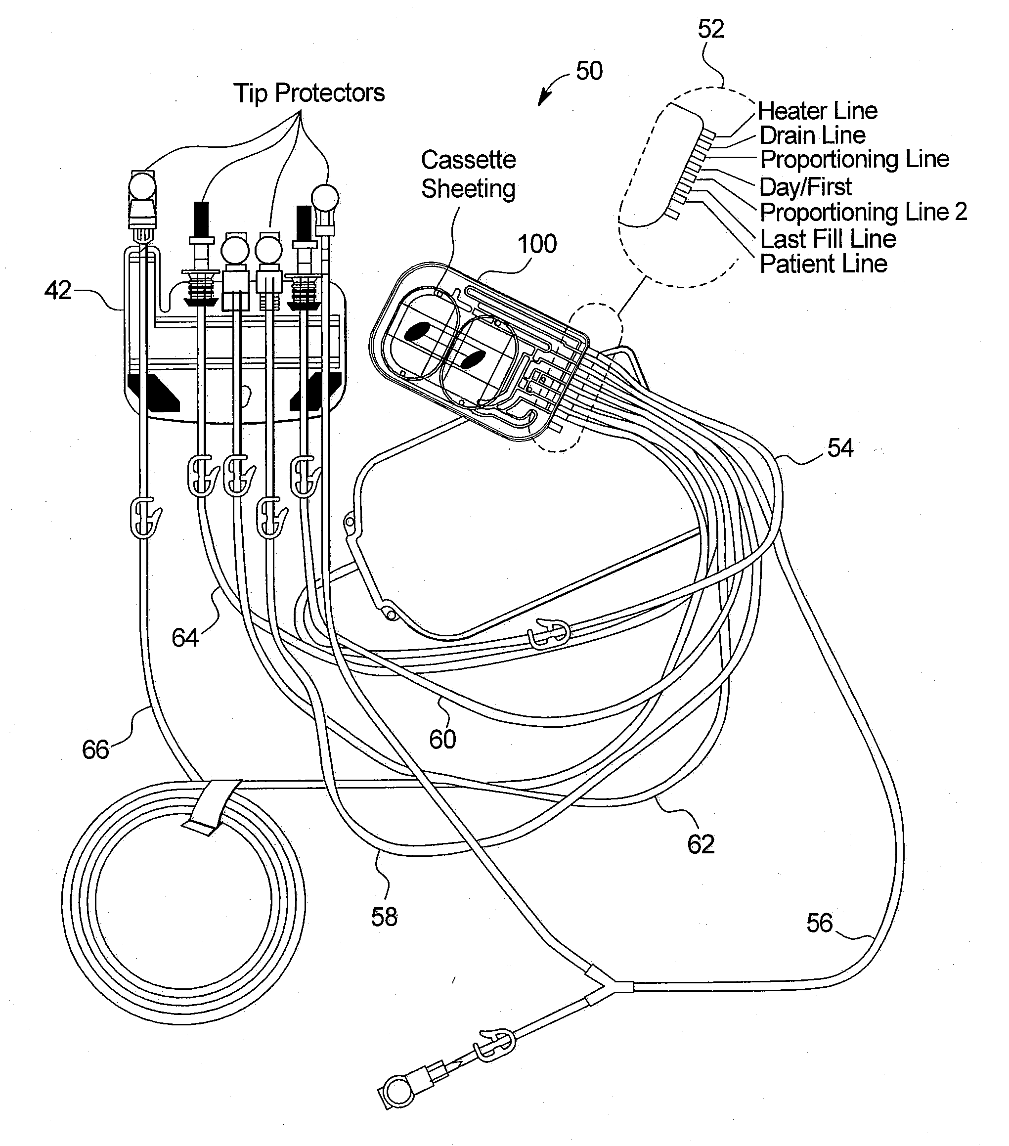
Peritoneal dialysis machine
a technology of peritoneal dialysis machine and dialysis chamber, which is applied in the field of medical fluid systems, can solve the problems of decreasing test time, and achieve the effects of reducing test time, reducing supplies, and being convenient for patients
- Summary
- Abstract
- Description
- Claims
- Application Information
AI Technical Summary
Benefits of technology
Problems solved by technology
Method used
Image

Examples
Embodiment Construction
[0047]One primary aspect of the present invention is an improved leak detection system for any type of cassette-based medical fluid therapy that exerts mechanical or pneumatic positive or negative pressure on a disposable fluid cassette. Another primary aspect of the present invention is an improved priming technique for a medical fluid therapy machine, such as an automated peritoneal dialysis (“APD”) system. While APD is one preferred use for the present invention, any cassette-based medical fluid system or system using a sterile, disposable fluid cartridge can employ the apparatuses and methods of the present invention. A further primary aspect of the present invention is to provide an apparatus and method for determining the head weight of the solution.
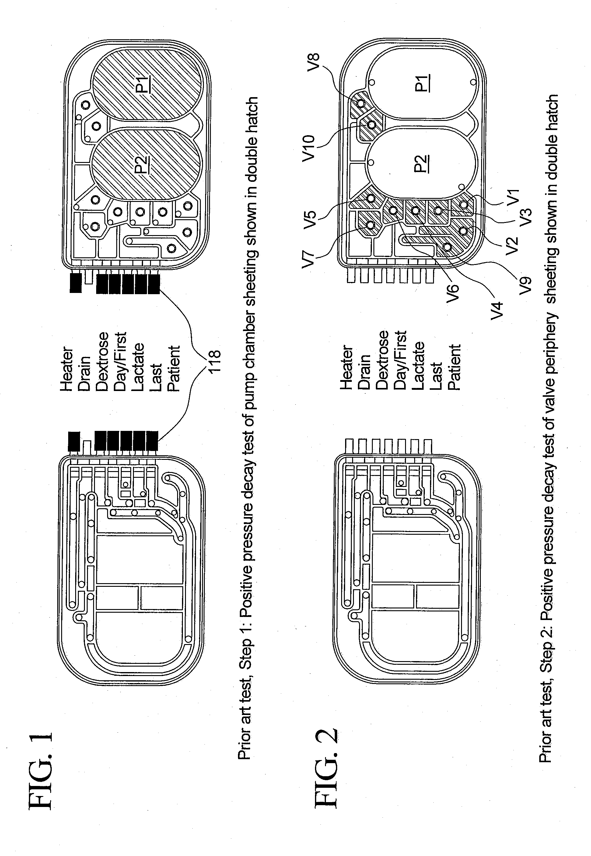
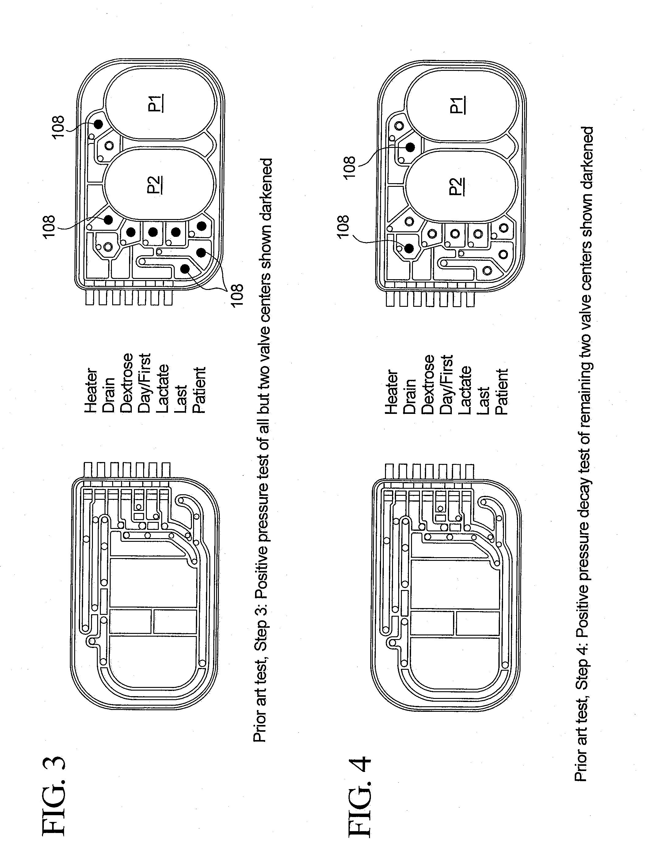
Improved Cassette-Based Leak Test
[0048]The following method is a “dry” method, which is more sensitive to leaks and other defects when compared to fluid based integrity testing. The method also eliminates some problems associated w...
PUM
 Abstract
Description
Claims
Application Information