

Method for measuring reactor bed level from active acoustic measurement and analysis
a technology of active acoustic measurement and reactor bed, which is applied in the direction of liquid/fluent solid measurement, machines/engines, instruments, etc., can solve the problems of large portion of the drum left unfilled and unused, and refineries that have difficulty in knowing the exact level of the drum run two risks, and achieve significant throughput loss and maintenance costs
- Summary
- Abstract
- Description
- Claims
- Application Information
AI Technical Summary
Benefits of technology
Problems solved by technology
Method used
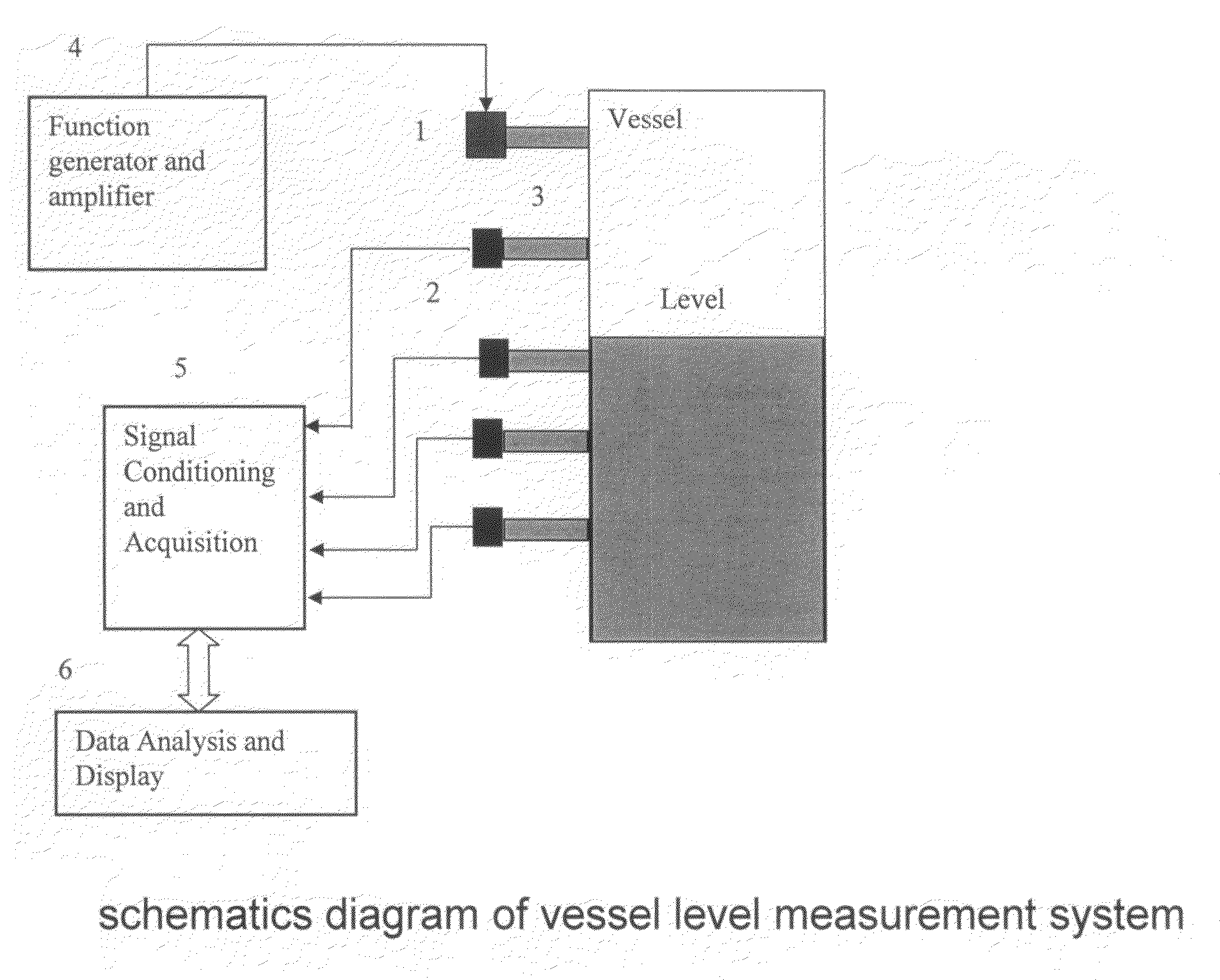
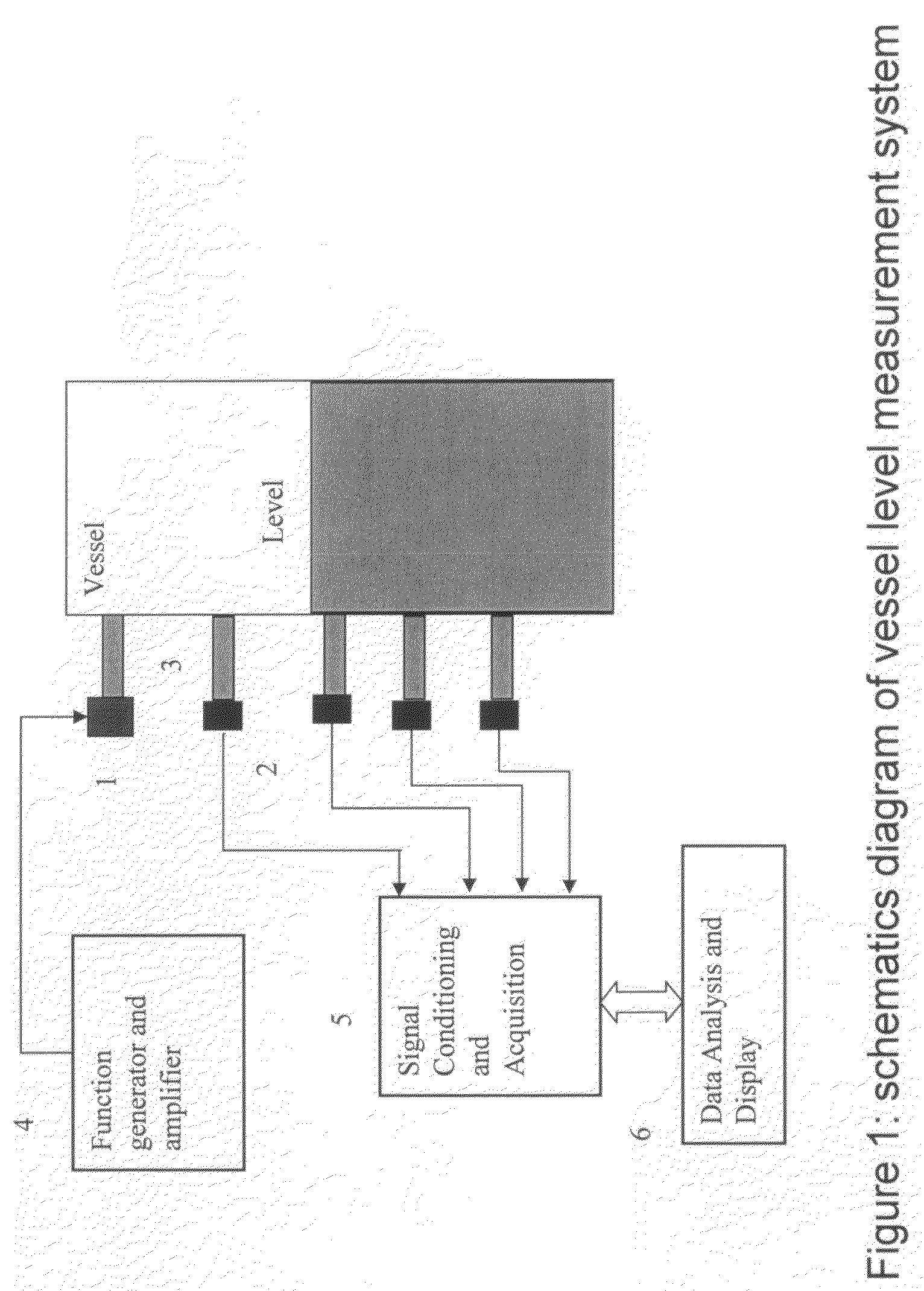
Image

Examples
example 1
Experiment Set-Up
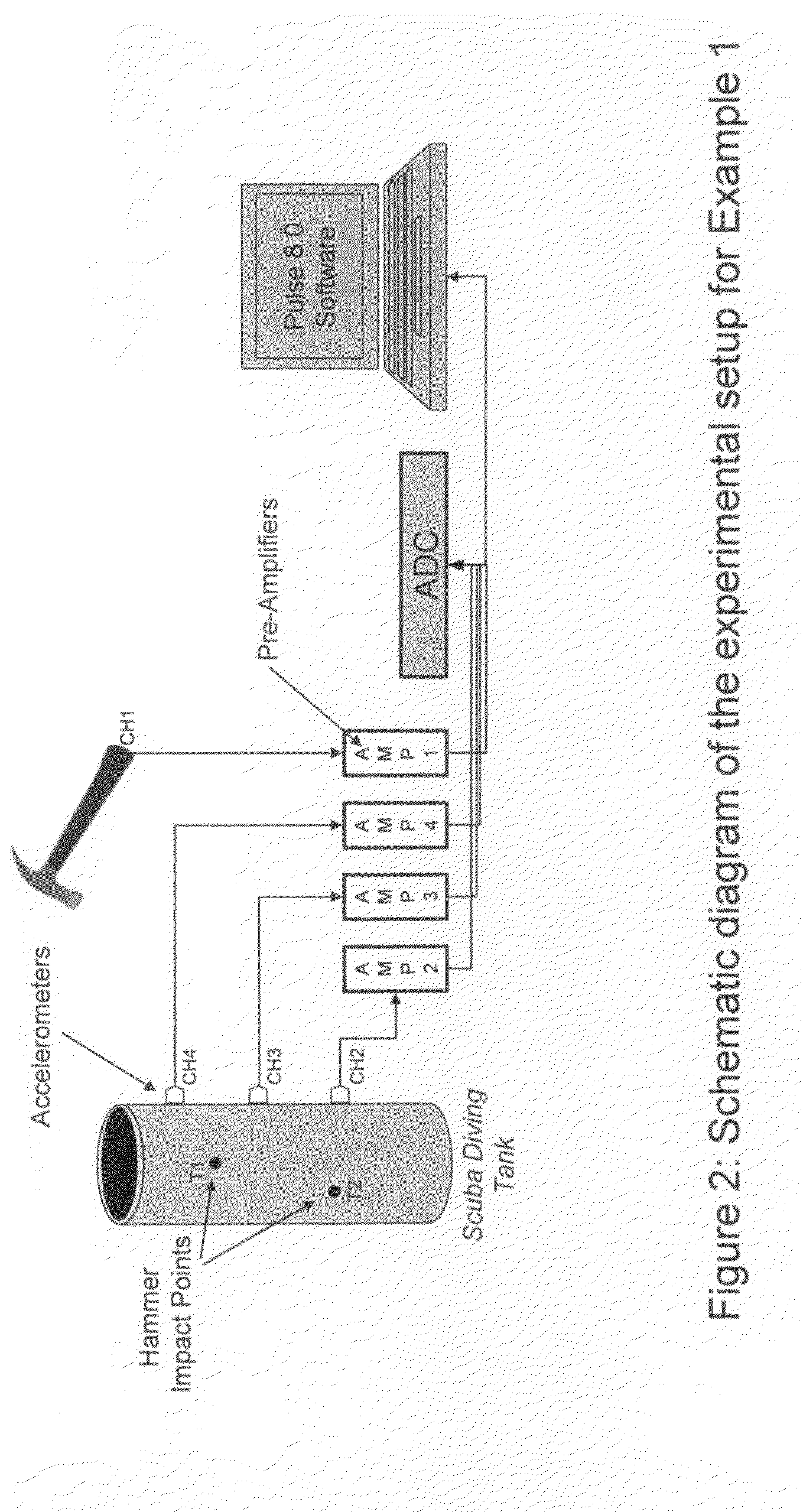
[0019]The experimental setup for a simulated delayed-coker consists of a SCUBA diving tank with an opening at the top (FIG. 2). The dimensions of the tank are 22 inches height and 7 inches ID. Three accelerometers CH2, CH3 and CH4 (Brüel & Kjaer 4384) were positioned on the outer surface equidistant along the y-axis of the scuba tank (6, 12 and 18 inches from the bottom of tank respectively). Each accelerometer was coupled to a charge amplifier (Brüel & Kjaer 2635) and the amplifiers connected to an analog-to-digital acquisition system controlled by Pulse 8.0 software (Brüel & Kjaer) installed in a portable computer. An instrumented impact hammer (Brüel & Kjaer 8202) was used to induce vibration of the tank. Two points of impact T1 (at the top of the tank) and T2 (at the middle of the tank) were chosen to determine the effect of different impact locations. The data was normalized to the impact force of the hammer. Normalized time-dependent data was converted to the ...
example 2
Water as Filling Media
[0020]FIG. 3 shows the frequency response functions of the wall vibration due to the hammer impact at various fill levels for the case of water filling up the scuba diving tank. As shown, multiple of vibration modes, identified as the peaks on the frequency response functions, are excited by the hammer impact. Each vibration mode is associated with two parameters: modal frequency and modal amplitude. Following a specific mode, a downward shift of the modal frequency with the water fill level is observed. FIG. 4 shows the correlation of the frequency of the first vibration mode with the fill level, measured with accelerometer at CH2 at hammer point of impact T1. In general, as the fill level increases, the modal frequency decreases. The change in the modal frequency with the fill level show that vibration data can be used to measure the fill level of similar systems.
[0021]A comparison between different accelerometer positions as well as impact points was also pe...
example 3
Shot Coke Saturated Solution as Filling Media
[0023]For the case of the mixture of coke with water, FIG. 6 shows plots of the modal frequency versus the fill level measured with CH2 at hammer point of impact T1. Again the same behavior as for the case of water-only is observed, i.e. the shift to lower modal frequencies with fill level. This trend is not only observed for this particular mode but also for other modes with the modal frequencies throughout the range of 1 to 12,000 Hz.
[0024]In general, both experiments (water-only and coke / water) show similar correlations. However, there are a few disparities between the experiments. For example, the frequency shift observed for the water-only case occurs within a range of about 260 Hz. On the other hand, for the case of coke plus water the frequency shift occurs within a range of about 410 Hz. This difference is expected due to the differences in the chemical composition of the filling media. For example, water is less dense than a satu...
PUM
 Abstract
Description
Claims
Application Information