Fluid dispenser

a dispenser and flue technology, applied in the field of flue dispensers, can solve the problem that it is practically impossible to unscrew the fastener member using reasonable torqu

Active Publication Date: 2009-11-19
APTAR FRANCE SAS
View PDF8 Cites 36 Cited by
  • Summary
  • Abstract
  • Description
  • Claims
  • Application Information

AI Technical Summary

Benefits of technology

[0005]An object of the present invention is to remedy the above-mentioned drawbacks of the prior art by defining a fluid dispenser having a fastener member that presents all the advantages of being capable of being unscrewed, without having the drawbacks needing to be screwed tight.

Problems solved by technology

If the skirt comes into contact with the threads of the neck over its entire periphery, it is practically impossible to unscrew the fastener member using reasonable torque, i.e. torque that it is possible to obtain by means of two hands.

Method used


Image

  • Fluid dispenser
  • Fluid dispenser
  • Fluid dispenser

Examples


Embodiment Construction

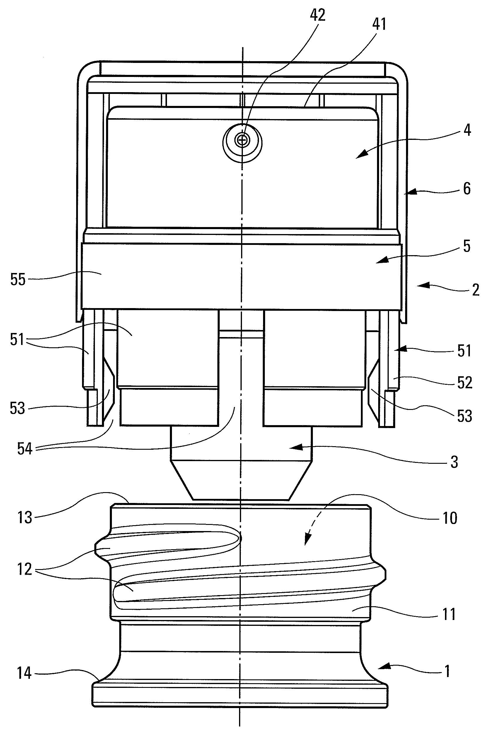
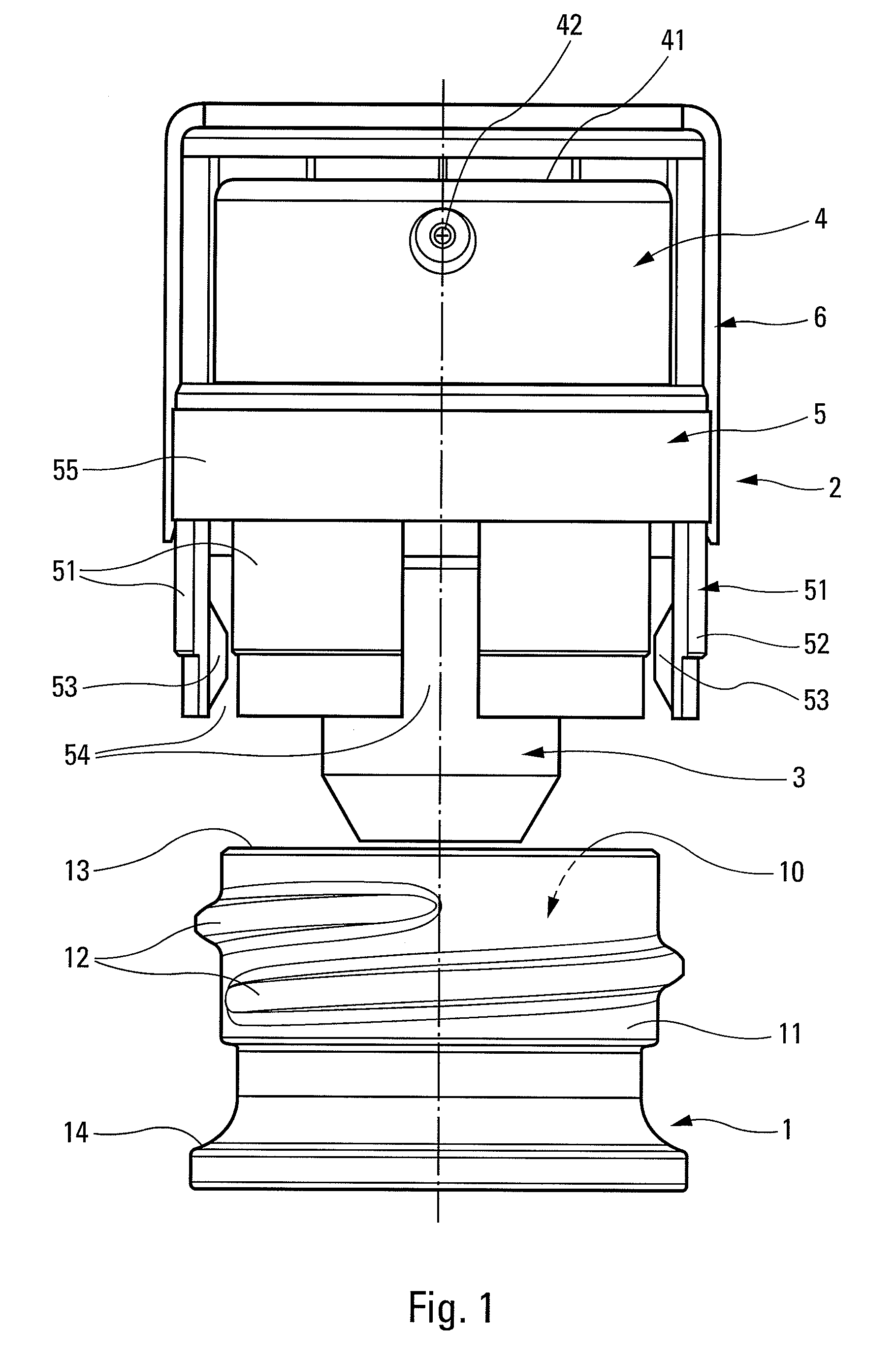
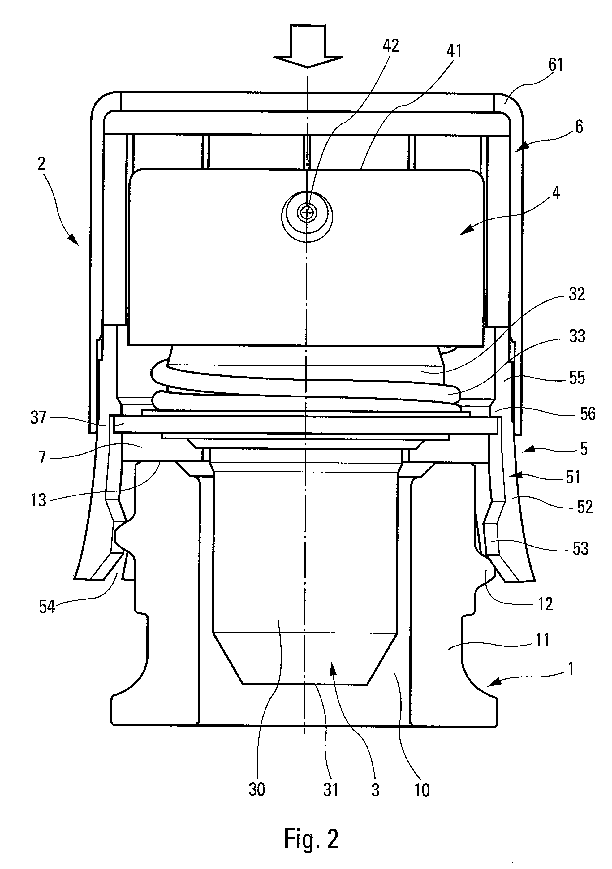
[0014]The fluid dispenser shown in the figures in order to illustrate the present invention comprises two distinct parts or sub-assemblies, namely a fluid reservoir 1 and a dispenser head 2 for mounting on the reservoir so as to co-operate with each other to constitute the dispenser.

[0015]The fluid reservoir 1 is shown in part only in the figures. Only the neck 11 and a portion of the shoulder 14 of the reservoir 1 is shown in the figures. The neck 11 projects axially upwards from the shoulder 14 that already forms a portion of the reservoir body (not shown). The neck 11 internally defines an opening 10 that puts the inside of the reservoir into communication with the outside. The opening 10 is defined by an annular top edge 13 of the neck 11. Externally, the neck 11 forms one or more helical threads 12 that are in the form of one or more projecting ribs disposed in helical manner. The threads 12 can extend over all or part of the periphery of the neck 11. The threads 12 can be cont...


PUM


Abstract

A fluid dispenser comprising: a fluid reservoir (1) provided with a neck (11) that is externally threaded and that internally defines an opening (10) that communicates with the inside of the reservoir, the neck (11) forming at least one helical thread (12); a dispenser head (2) mounted on the neck (11) of the reservoir (1), the head (2) comprising: a dispenser member (3), such as a pump or a valve; a pusher (4) for actuating the dispenser member (3); and a fastener member (5, 6) engaged both with the threaded neck (11) of the reservoir (1) and with the dispenser member; the fluid dispenser being characterized in that the fastener member (5, 6) comprises: a deformable and malleable skirt (51) for coming into engagement with the threaded neck (11); and a rigid hoop (6) that is engaged around the skirt (51) so as to push the skirt radially against the threaded neck (11) in such a manner as to deform the skirt (51) against the thread (12) so as to create a thread imprint (530) in the skirt.

Description

CROSS REFERENCE TO RELATED APPLICATION[0001]This application claims the benefit under 35 U.S.C. §119(e) of pending U.S. provisional patent application Ser. No. 61 / 089,129, filed Aug. 15, 2008, and priority under 35 U.S.C. §119(a)-(d) of French patent application No. FR-08.53221, filed May 19, 2008.TECHNICAL FIELD[0002]The present invention relates to a fluid dispenser comprising: a fluid reservoir provided with a neck that is externally threaded and that internally defines an opening that communicates with the inside of the reservoir. The dispenser further comprises a dispenser head mounted on the neck of the reservoir, the head comprising: a dispenser member, such as a pump or a valve; a pusher for actuating the dispenser member; and a fastener member engaged both with the threaded neck of the reservoir and with the dispenser member. Such dispensers are frequently used in the fields of perfumery, cosmetics, or even pharmacy.BACKGROUND OF THE INVENTION[0003]In general, the fastener ...

Claims


Application Information

Patent Timeline
Patent Type & Authority Applications(United States)
IPC IPC(8): B65D88/54B65D41/04
CPCB05B11/001B05B11/3049B05B11/3047B05B11/1049
Inventor BERANGER, STEPHANE
Owner APTAR FRANCE SAS
Why Eureka
Try Eureka