Illumination optical system and image projector using same
an optical system and image technology, applied in the field of illumination optical systems, can solve the problems of reducing illumination efficiency and difficult molding of fly eye lenses, and achieve the effect of bright illumination of illuminated surfaces, high efficiency and no significant loss of light amoun
- Summary
- Abstract
- Description
- Claims
- Application Information
AI Technical Summary
Benefits of technology
Problems solved by technology
Method used
Image
Examples
first embodiment
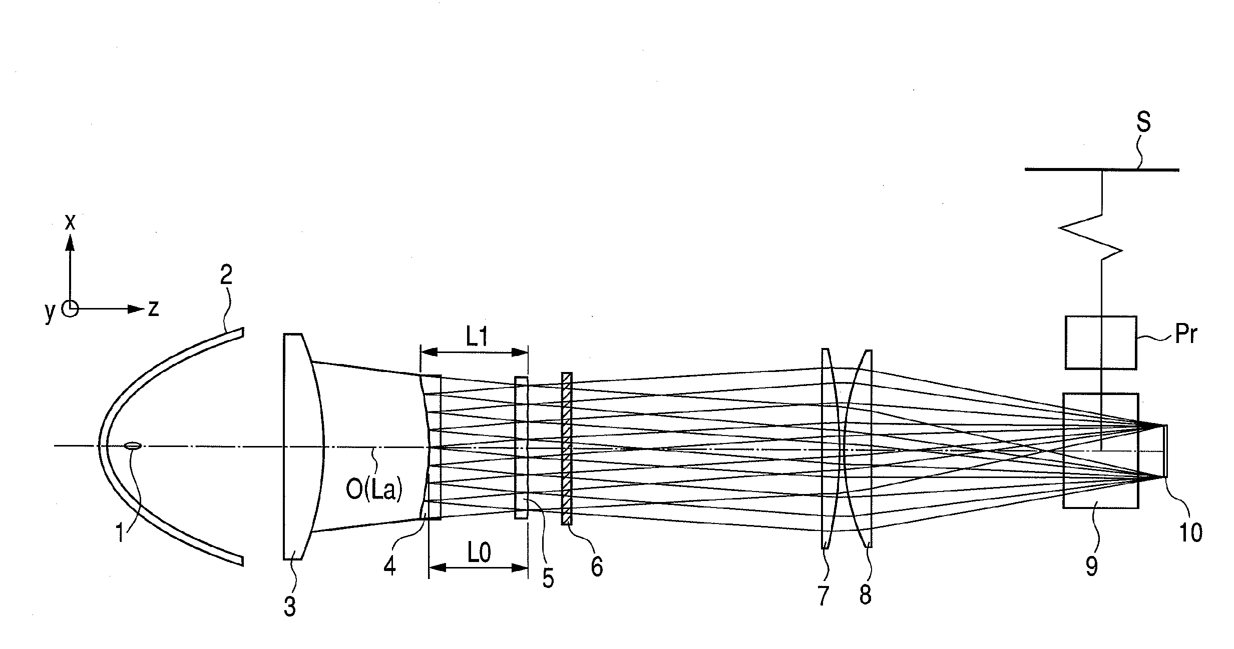
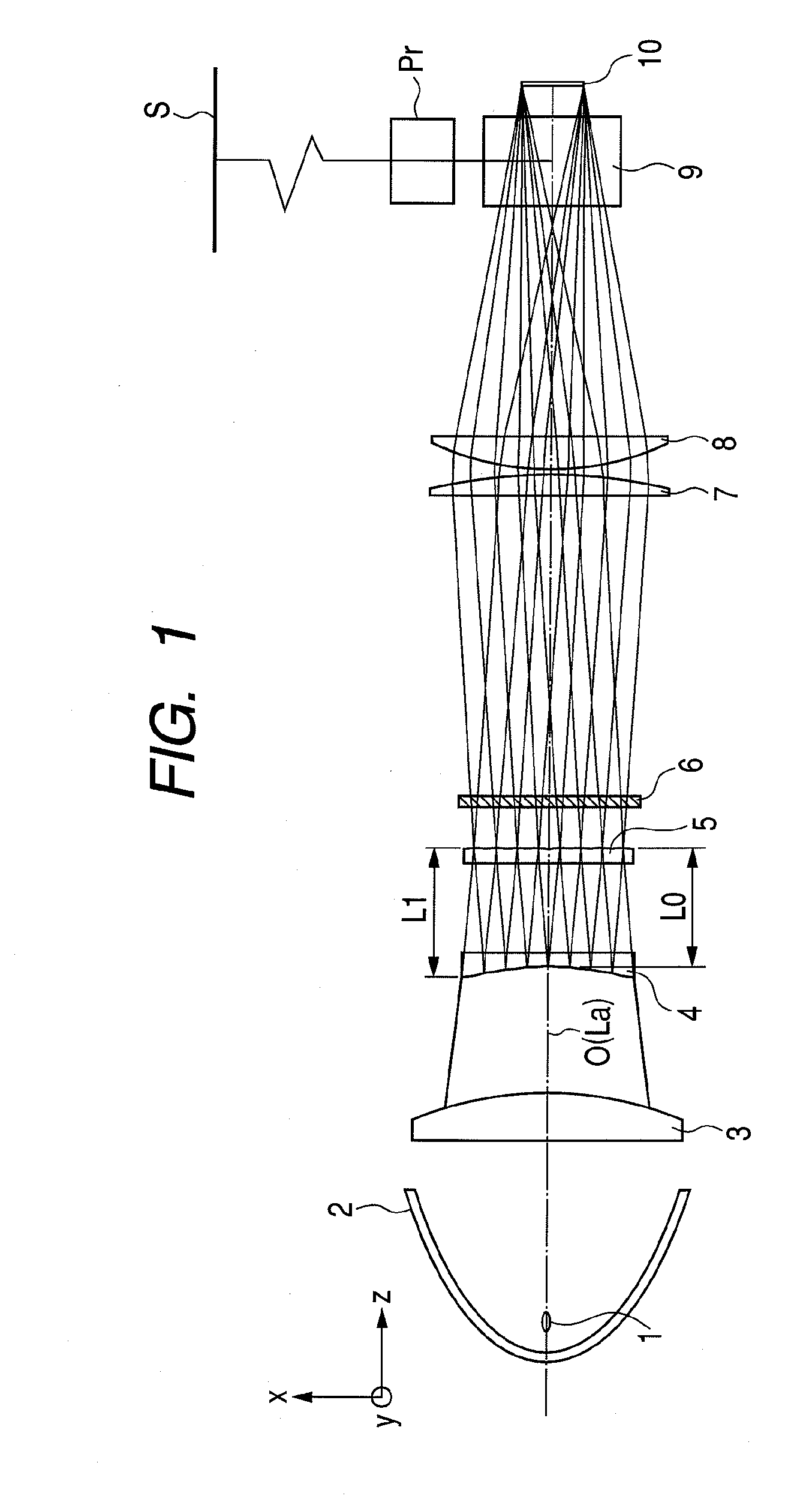
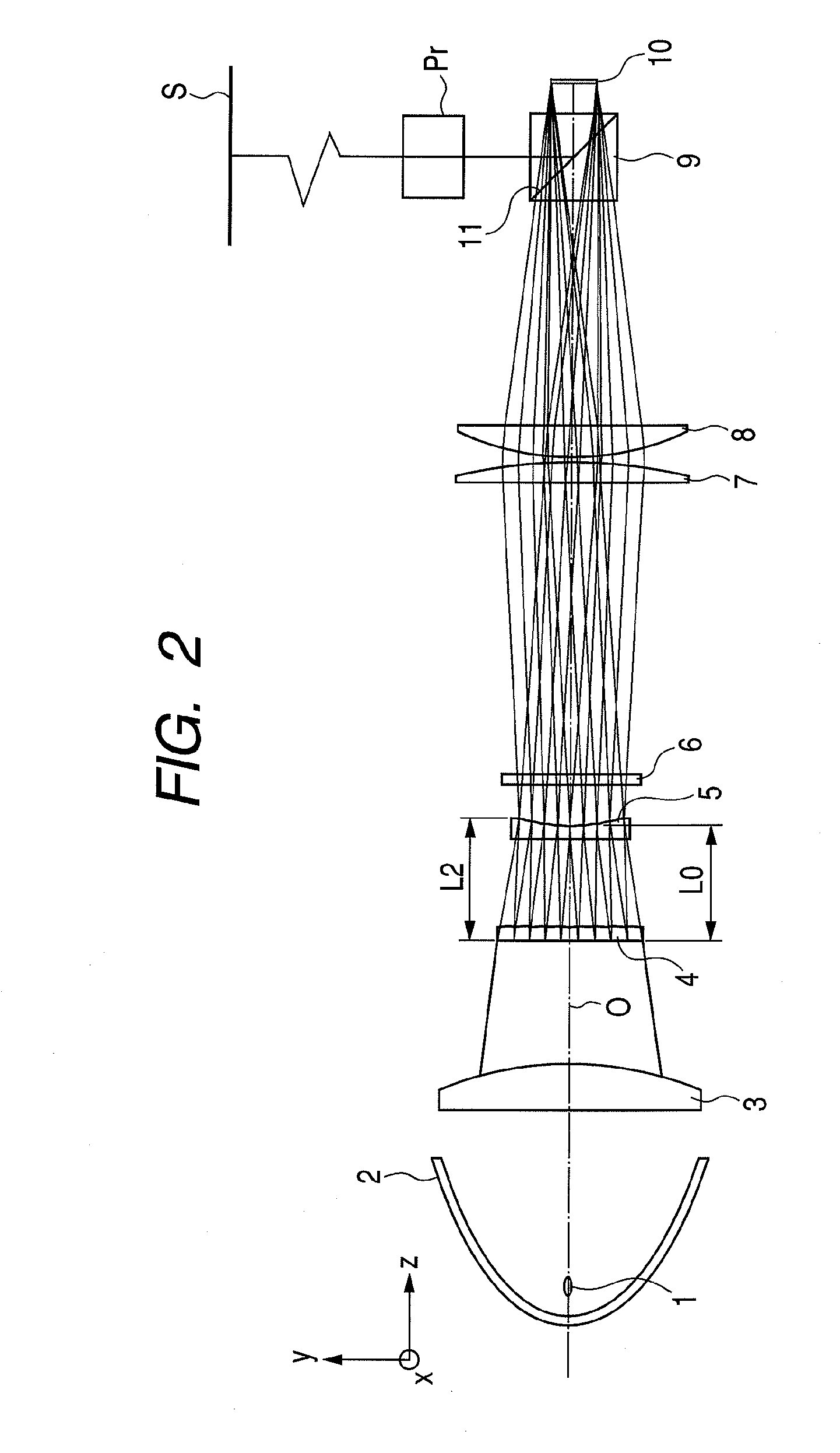
[0040]FIG. 1 schematically illustrates the relevant portions of an image projector having an illumination optical system according to a first embodiment of the present invention. FIG. 1 shows a cross section taken on a plane containing the center axis 0 (or the optical axis La) FIG. 2 also illustrates the relevant portions of the image projector in a cross section taken on a plane containing the center axis 0 in FIG. 1 and perpendicular to the plane of FIG. 1.
[0041]The illumination optical system according to this embodiment has a condenser that converges the light emitted from a light source so that convergent light emerges from the condenser and a collimator that collimates the light emerging from the condenser so that parallel light emerges from the collimator.
[0042]The illumination optical system further has a polarization conversion element that aligns (or uniformizes) the polarization state of light emerging from the collimator and a condenser lens system that condenses light ...
second embodiment
[0129]FIG. 10 schematically illustrates the relevant portions of an image projector having an illumination optical system according to a second embodiment of the present invention. FIG. 11 also illustrates the relevant portions of the image projector in a cross section taken on a plane containing the center axis 0 (optical axis La) in FIG. 10 and perpendicular to the plane of FIG. 10.
[0130]The basic configuration and components used in the second embodiment are the same as those in the first embodiment except for the first and second fly eye lenses 45, 46.
[0131]In the first embodiment, the first and second fly eye lenses 45, 46 are arranged in such a way that fly eye lens surfaces face away from each other. The second embodiment differs from the first embodiment in that the fly eye lens surfaces are arranged to face each other.
[0132]In FIGS. 10 and 11, elements the same as those in FIGS. 1 and 2 are denoted by the same reference signs.
[0133]The constitutions of first and second fly ...
third embodiment
[0143]FIG. 13 schematically illustrates the relevant portions of an image projector having an illumination optical system according to a third embodiment of the present invention. FIG. 14 also illustrates the relevant portions of the image projector in a cross section taken on a plane containing the center axis 0 (or optical axis La) in FIG. 13 and perpendicular to the plane of FIG. 13.
[0144]The basic configuration and components used in the third embodiment are the same as those in the first embodiment except for the first and second fly eye lenses 59.
[0145]In FIGS. 13 and 14, elements the same as those in FIGS. 1 and 2 are denoted by the same reference signs.
[0146]The constitution of a first fly eye lens 4 is the same as the first fly eye lens 4 used in the first embodiment. A second fly eye lens 59 has a cylindrical surface having a negative refracting power in the y-z plane on the incidence side and a fly eye lens having lens cells arranged two-dimensionally in the x-y plane on ...
PUM
 Abstract
Description
Claims
Application Information
 - R&D
- Intellectual Property
- Life Sciences
- Materials
- Tech Scout
- Unparalleled Data Quality
- Higher Quality Content
- 60% Fewer Hallucinations
Browse by: Latest US Patents, China's latest patents, Technical Efficacy Thesaurus, Application Domain, Technology Topic, Popular Technical Reports.
© 2025 PatSnap. All rights reserved.Legal|Privacy policy|Modern Slavery Act Transparency Statement|Sitemap|About US| Contact US: help@patsnap.com


