Soil reinforcing retaining wall anchor

a technology of reinforcing retaining walls and soil, applied in mining structures, excavations, artificial islands, etc., can solve the problems of poor connection contact between anchor and reinforcing mat, misalignment of anchors, and useless concrete panels

Inactive Publication Date: 2009-11-19
T & B STRUCTURAL SYST
View PDF3 Cites 14 Cited by
  • Summary
  • Abstract
  • Description
  • Claims
  • Application Information

AI Technical Summary

Problems solved by technology

A potentially serious problem emerges, however, when a single-loop facing anchor and the corresponding end of a soil reinforcing mat fail to align properly.
In the field, however, it is not uncommon to encounter anchors that are misaligned relative to the ends of the soil reinforcing mats or are otherwise misplaced or bent.
In well compacted backfills, the configuration (e.g., squareness) of the grid-like reinforcing mats will be fixed and virtually unable to deform to connect properly to a bent or misplaced anchor, rendering the concrete panel useless.
However, if the anchors are positioned incorrectly, poor connection contact between anchor and reinforcing mat will occur and the stress transfer to the longitudinal wires will not be uniform and proportional.
The above-described misalignment results in significantly higher tensile stresses in the working wires than if all connections were made equally.
This uneven stress distribution, due to poor transfer load at the connection, may result in seriously overstressed reinforcing wires that may lead to tensile failure of the welded wire reinforcing mats.
Bending the reinforcement mat wires or the facing anchors to create a connection does not solve this problem as it only results in poor conformance to tolerances.
Certainly in those instances an uneven stress distribution will occur at the panel connection and may result in a future soil reinforcement failure.
Whether cast into the concrete on site or in a manufacturing facility, the single-loop facing anchors are prone to both horizontal and vertical misalignment, in addition to axial twisting and inconsistent depth placement.

Method used


Image

  • Soil reinforcing retaining wall anchor
  • Soil reinforcing retaining wall anchor
  • Soil reinforcing retaining wall anchor

Examples


Embodiment Construction

[0018]It is understood that the following disclosure provides several different embodiments, or examples, for implementing different features of the disclosure. Specific examples of components and arrangements are described below to simplify the present disclosure. These are, of course, merely examples and are not intended to be limiting. In addition, the present disclosure may repeat reference numerals and / or letters in the various examples. This repetition is for the purpose of simplicity and clarity and does not in itself dictate a relationship between the various embodiments and / or configurations discussed.

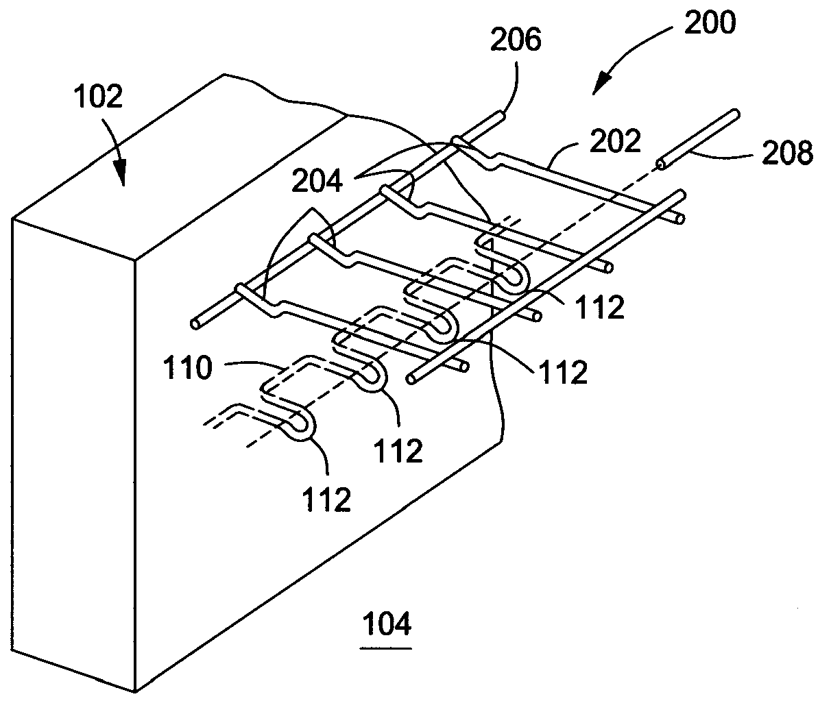
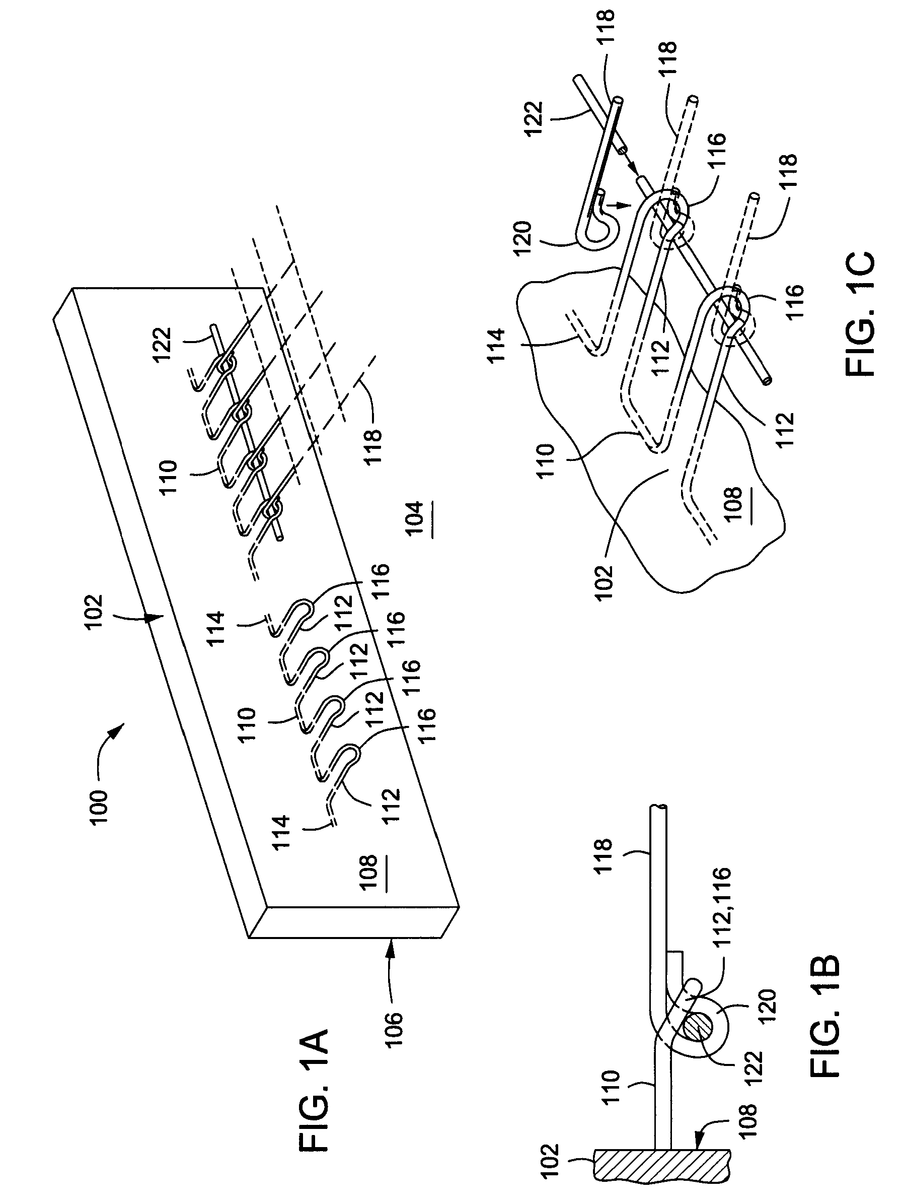
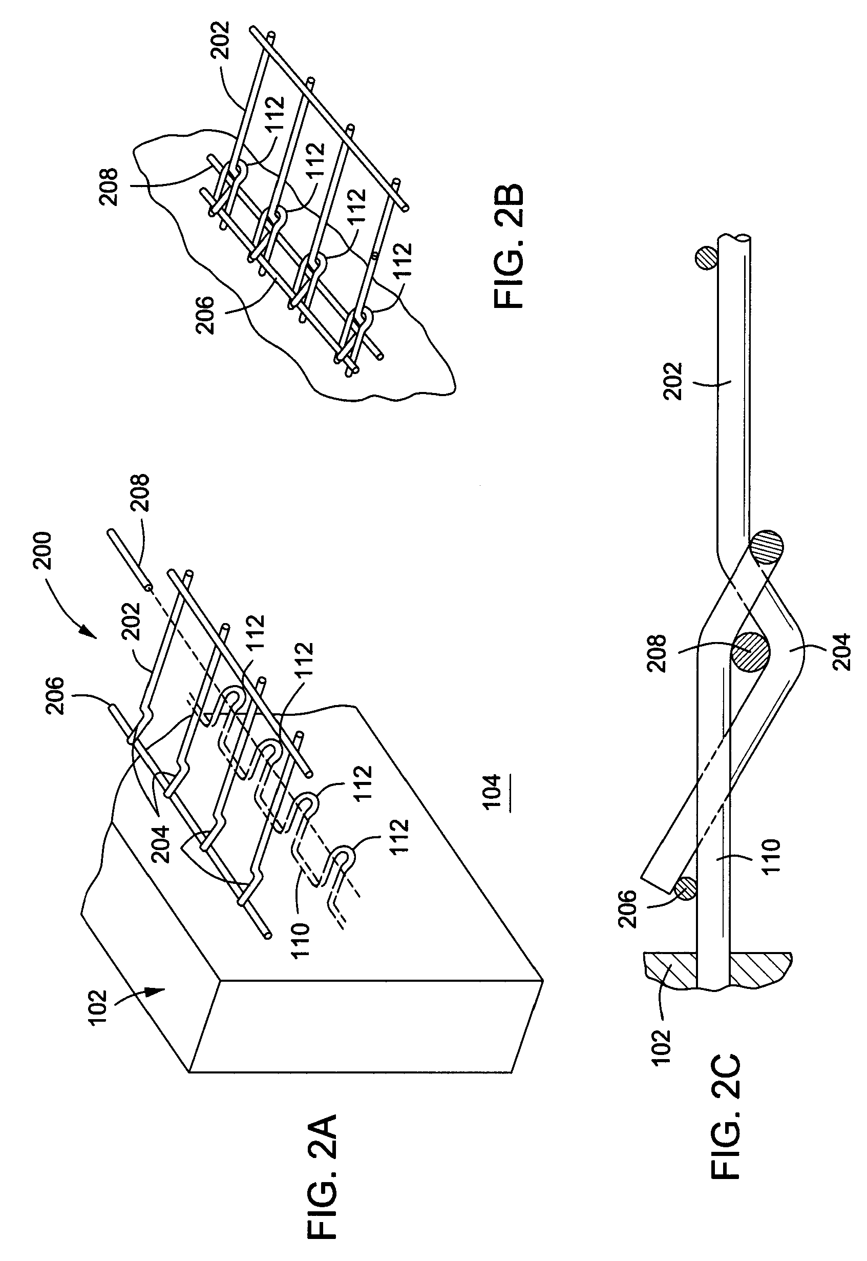
[0019]The present disclosure may be embodied as an improved apparatus and method of connecting an earthen formation to a concrete facing of a MSE structure. In particular, the facing of the MSE may comprise either a series of concrete panels stacked one atop the other or a uniform, unbroken expanse of concrete. In either case, the back of the concrete facing may comprise at le...


PUM


Abstract

A facing anchor for securing a soil reinforcing element to a facing comprising an unbroken length of continuous wire originating with a pair of lateral extensions cast into a concrete wall and including a series of loops extending from the concrete wall, wherein the loops each include an angularly inclined distal end segment configured to receive corresponding ends of the soil reinforcing element.

Description

CROSS-REFERENCE TO RELATED APPLICATION[0001]This application is related to commonly-owned and concurrently filed U.S. Design Patent Application No. ______, entitled “SOIL REINFORCING RETAINING WALL ANCHOR,” Attorney Docket No. 21801.30.BACKGROUND OF THE DISCLOSURE[0002]Retaining wall structures that use horizontally positioned soil inclusions to reinforce an earth mass in combination with a facing element are referred to as Mechanically Stabilized Earth (MSE) structures. MSE can be used for various applications including retaining walls, bridge abutments, dams, seawalls, and dikes.[0003]The basic MSE technology is a repetitive process where layers of backfill and horizontally placed soil reinforcing elements are positioned one atop the other until a desired height of the earthen structure is achieved. Typically, grid-like steel mats or welded wire mesh are used as reinforcement elements. In most applications, the reinforcing mats consist of parallel transversely extending wires weld...

Claims


Application Information

Patent Timeline
Patent Type & Authority Applications(United States)
IPC IPC(8): E21D20/00E02D17/00
CPCE02D29/0241
Inventor TAYLOR, THOMAS P.BAGWELL, JAMES SCOTT
Owner T & B STRUCTURAL SYST
Why Eureka
Try Eureka