Pill counting tray

a pill and trough technology, applied in the direction of oral administration devices, etc., can solve the problems of pill counting tray not providing a user with visual references, botched seeming simple tasks, and mixing of pill counts,

Inactive Publication Date: 2009-11-19
CHEMEL DARRYL
View PDF16 Cites 6 Cited by
  • Summary
  • Abstract
  • Description
  • Claims
  • Application Information

AI Technical Summary

Benefits of technology

[0014]In some embodiments the second support surface is permitted to slide between complimentary right and left positions to ease right and left-handed operation as desired by a user. In some embodiments the side wall further comprises upper fins serving as a side guard to restrict the motion of the second support surface and to prevent pills from spilling out of the apparatus over edges of the second support surface. In some embodiments a portion of the sidewall includes a substantially horizontal lip to support sliding movement of the second support surface. In some embodiments the horizontal lip includes a slide groove to permit and restrict the sliding movement of the second support surface.
[0018]In some embodiments the sidewall includes upper fins flanking the first pouring spout and extending towards the interior of the pan. In some embodiments the second support surface includes an upwardly extending lip that, after assembly, fits underneath the upper fins of the pan and is shaped to conform to the interior surface of the sidewall to prevent pills on the tray from sliding through the first pouring spout.

Problems solved by technology

This seemingly simple task is often botched because even gently bumping and / or nudging the tray may lead to spillage and / or intermixing of the counted pills with the excess bulk pills.
The pill counting tray does not provide a user with visual references that can be to distinguish between different groups of pills.
Subsequently, a pharmacist may make mistakes when using the asymmetric pill counting tray disclosed by Zaleon.
Once the pills are separated into the two compartments it is difficult to visually determine which compartment has the counted pills or the excess bulk pills.
Second, a pharmacist may be distracted or interrupted and forget which compartment is being used for each group of pills.

Method used


Image

  • Pill counting tray
  • Pill counting tray
  • Pill counting tray

Examples


Embodiment Construction

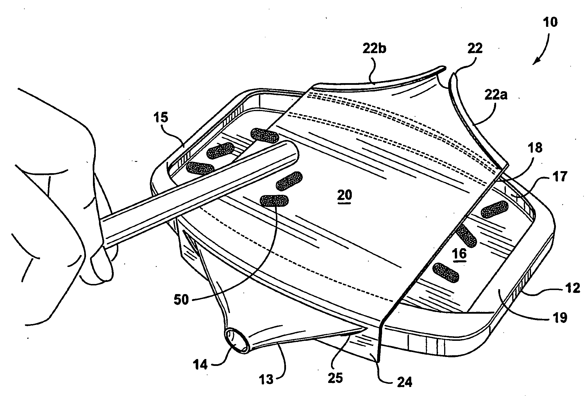
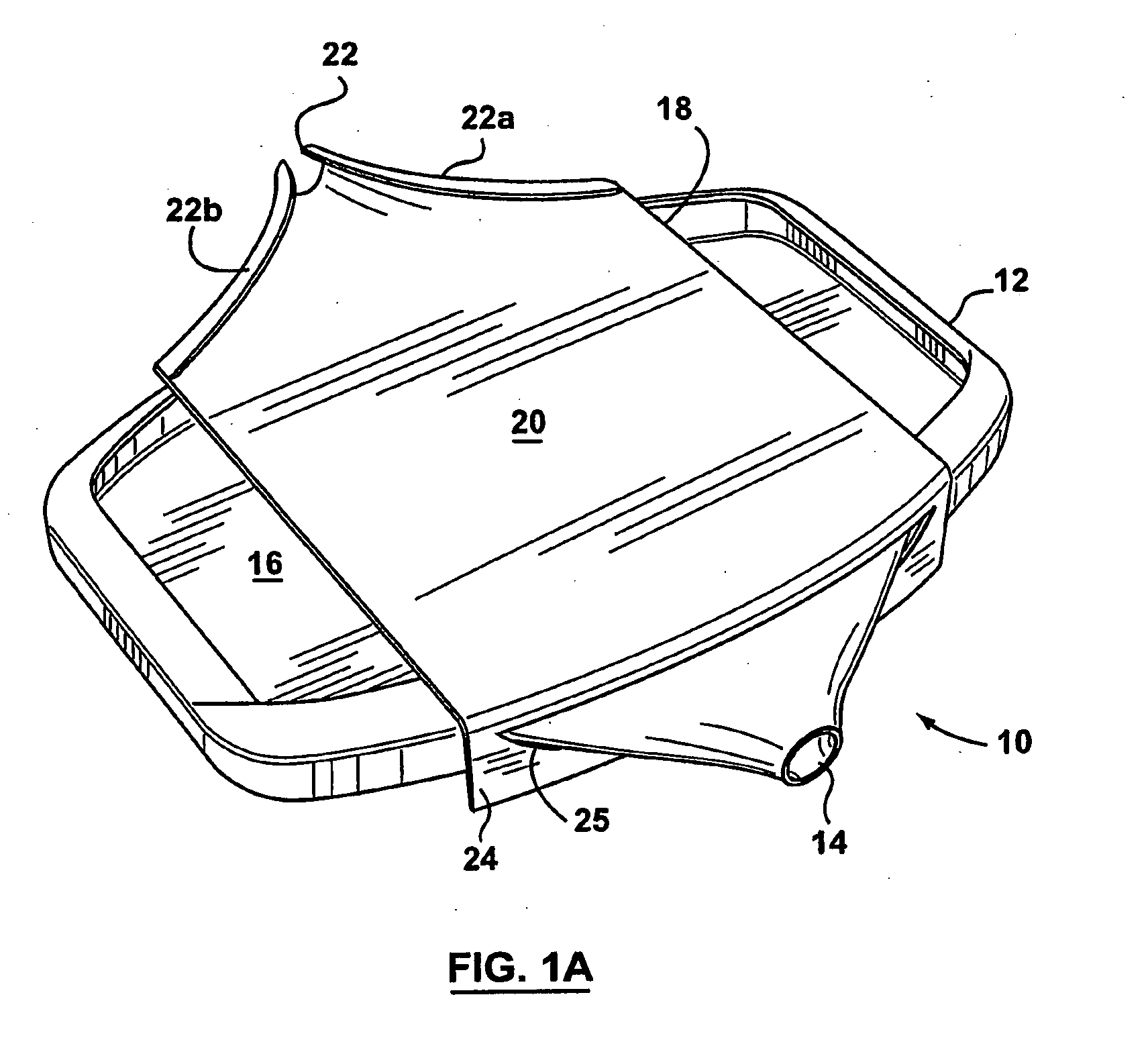
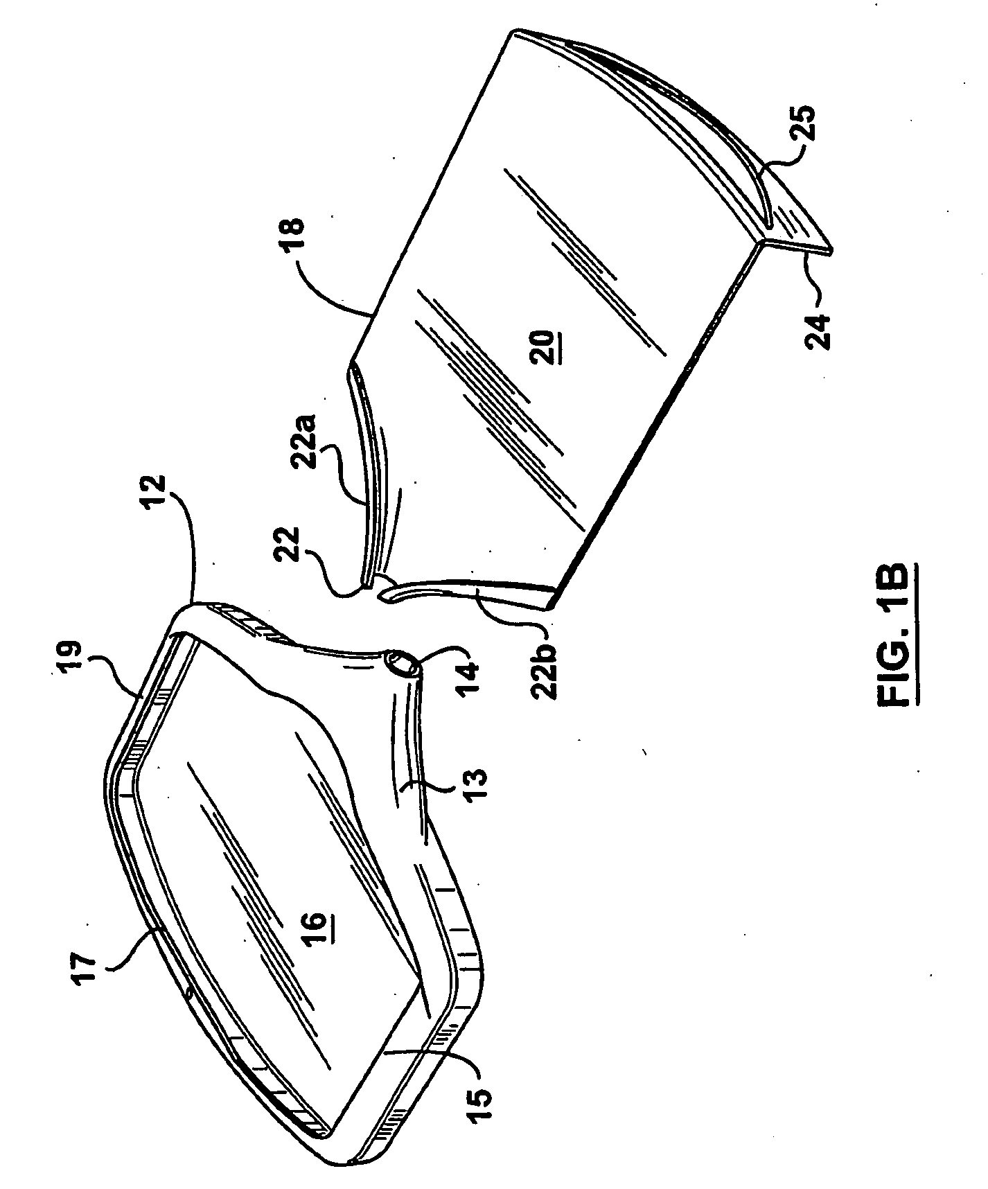
[0030]Most conventional pill counting devices are intentionally designed to be ergonomically comfortable for either right or left-handed users, but not both right and left-handed users simultaneously. In contrast, some embodiments in accordance with the invention provide a pill counting apparatus that is ergonomically comfortable for both right and left-handed users a like. In such embodiments the construction of a pill counting apparatus provides clear and inherent visual queues that enable a user to easily distinguish counted pills from bulk pills.

[0031]In some embodiments a pill counting apparatus includes a first support surface and a second support surface elevated over the first support surface. At least one of the first and second support surfaces has a pouring spout. In more specific embodiments the first and second support surfaces have a respective first and second pouring spouts that encourage pouring in different directions from one another.

[0032]In some embodiments the ...


PUM


Abstract

Most conventional pill counting devices are intentionally designed to be ergonomically comfortable for either right or left-handed users, but not both right and left-handed users simultaneously. In contrast, some embodiments in accordance with the invention provide a pill counting apparatus that is ergonomically comfortable for both right and left-handed users a like. In such embodiments the construction of the pill counting apparatus provides clear and inherent visual queues that enable a user to easily distinguish counted pills from bulk pills. In some embodiments a pill counting apparatus includes a pan with a symmetrically arranged first pouring spout and a tray having a symmetrically arranged second pouring spout, and the first and second pouring spouts are arranged to encourage pouring in different directions from one another.

Description

FIELD OF THE INVENTION[0001]The invention relates to apparatus for counting pills and the like, and, in particular to pill counting trays.BACKGROUND OF THE INVENTION[0002]The most widely used apparatus employed by pharmacists for counting out pills and the like (e.g. tablets, pellets, capsules, lozenges, etc.) is a simple flat counting tray having a collection trough integrally connected along one side of the tray. A well-known example of such a pill counting tray is disclosed in U.S. Pat. No. 2,530,009 to Fields. In use, a bulk supply of pills is poured onto the tray and a desired amount of pills is then counted and pushed into the trough using a spatula. The counted pills in the trough are transferred into a prescription bottle (or similar vessel) preferably without spilling the excess bulk pills remaining on the tray. This seemingly simple task is often botched because even gently bumping and / or nudging the tray may lead to spillage and / or intermixing of the counted pills with th...

Claims


Application Information

Patent Timeline
Patent Type & Authority Applications(United States)
IPC IPC(8): A61J7/02
CPCA61J7/02
Inventor CHEMEL, DARRYL
Owner CHEMEL DARRYL
Why Eureka
Try Eureka