Reduced thickness injection moulded part design

a technology of injection moulding and parts, applied in the direction of paper/cardboard containers, boxes, containers, etc., can solve the problems of poor part quality and the approach doesn't work well with parts

Inactive Publication Date: 2009-11-19
STACKTECK SYST LTD
View PDF2 Cites 21 Cited by
  • Summary
  • Abstract
  • Description
  • Claims
  • Application Information

AI Technical Summary

Problems solved by technology

Such an approach however doesn't work well with parts in which weight reduction through very thin walls is desired.
As described in more detail below, once the disparity in flow rates between the thinner and thicker areas exceeds a certain amount poor part quality can ensue.

Method used


Image

  • Reduced thickness injection moulded part design
  • Reduced thickness injection moulded part design
  • Reduced thickness injection moulded part design

Examples


Embodiment Construction

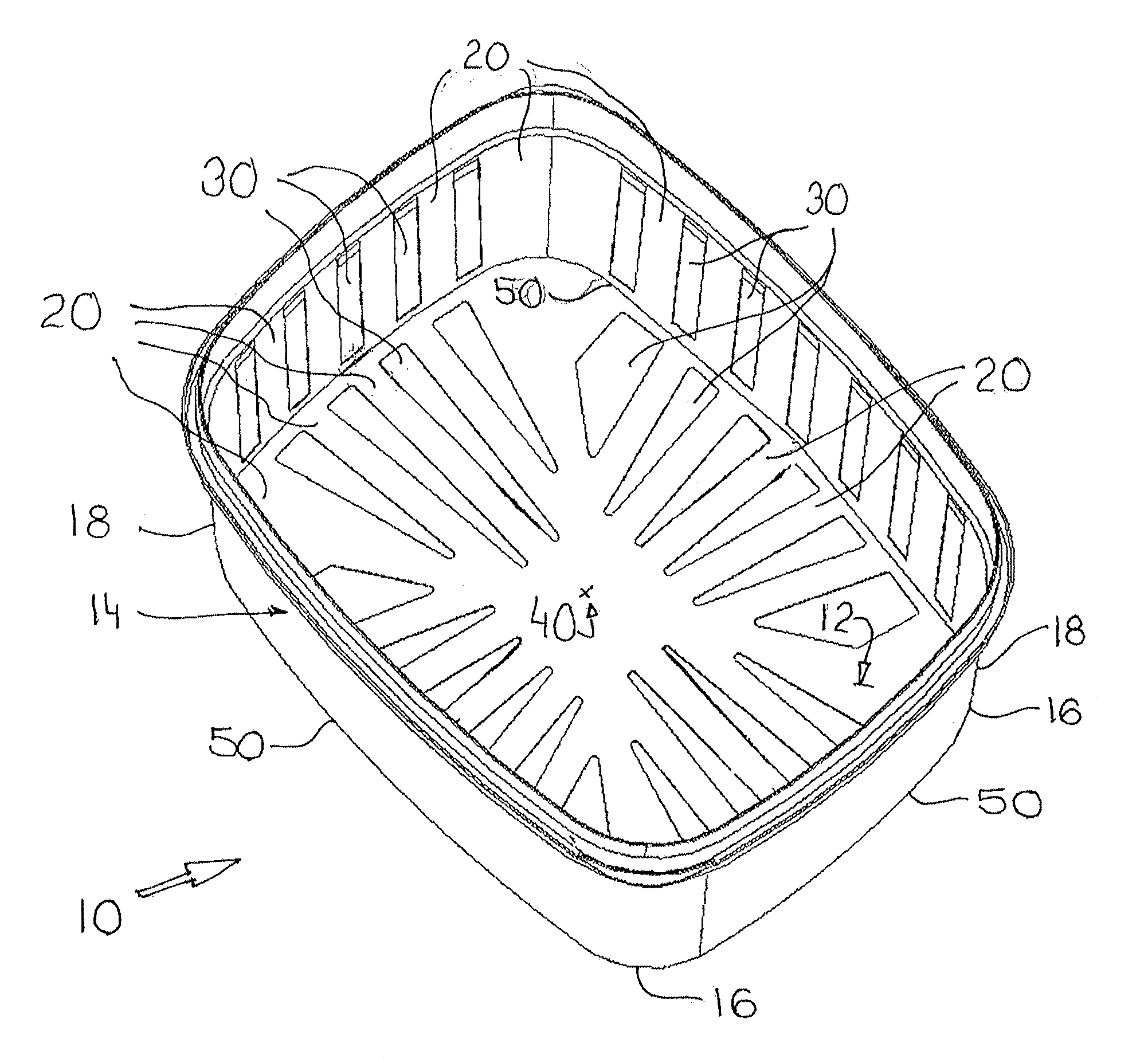
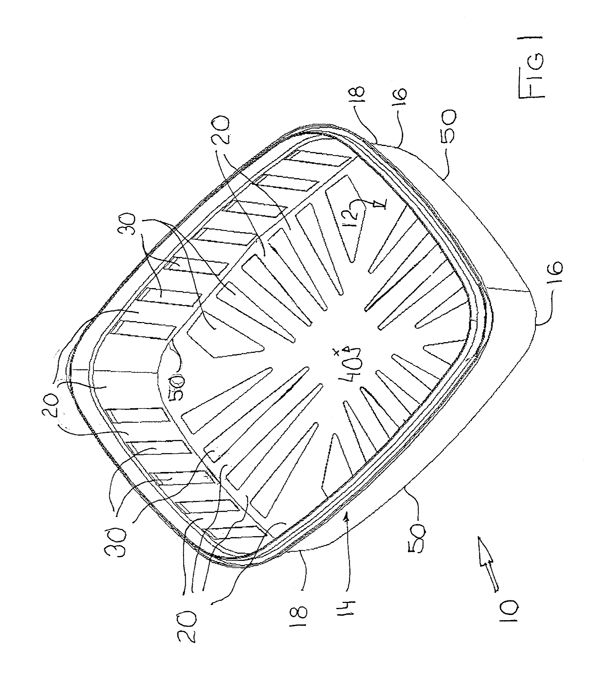
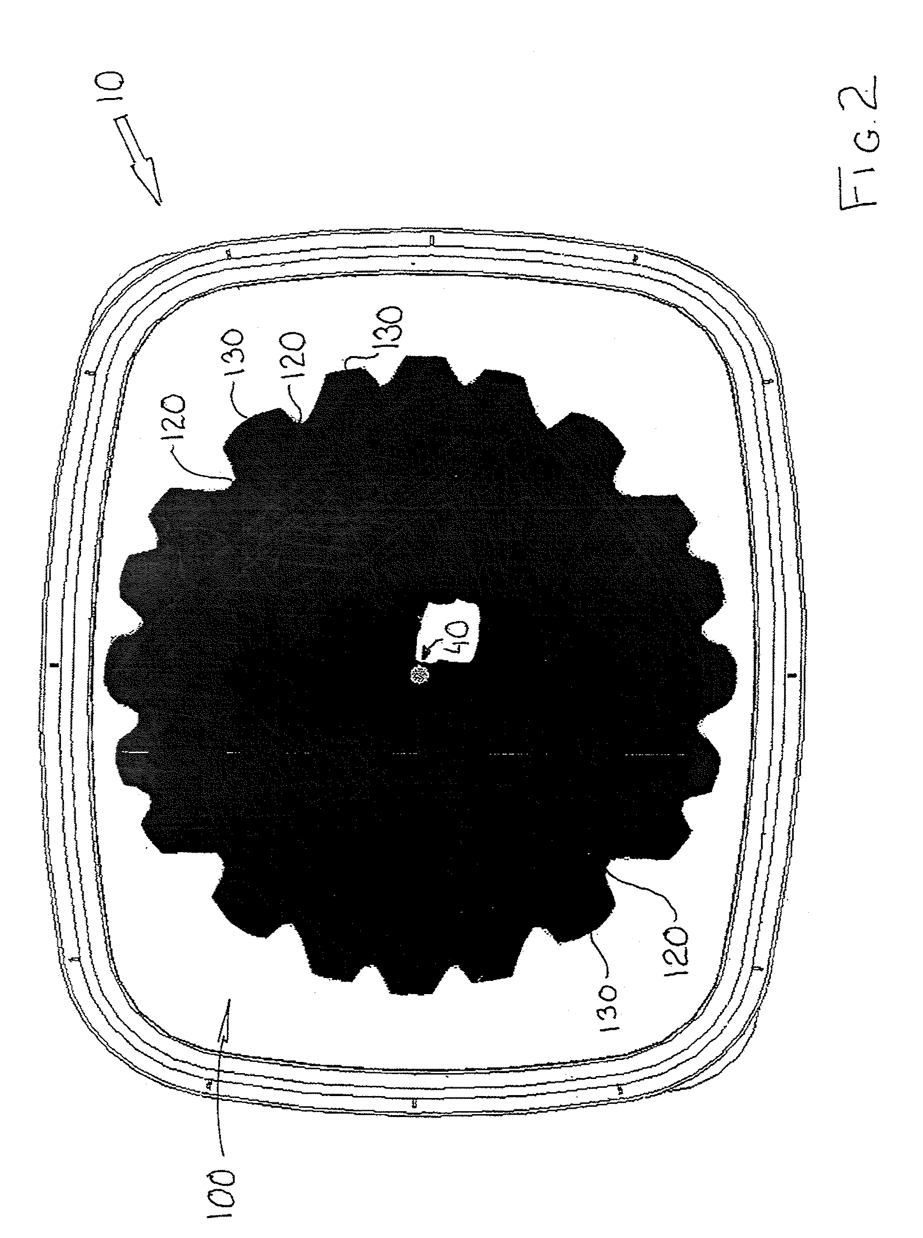
[0016]An injection moulded part according to the present invention is generally indicated by reference 10 in the accompanying illustrations. The part 10 is illustrated as a container with a bottom 12 and a side wall 14. Other parts are however feasible including, without limitation containers, closures, cups, pails, buckets and long flat parts which have no side wall portion such as lids, trays, etc. All shapes such as round, oval, rectangular, etc. are also feasible.

[0017]The part 10 comprises a continuous surface defined by an alternating arrangement of thicker panels 20 and thinner panels 30. The thinner panels 20 and thicker panels 30 extend from a gate area 40 which corresponds to where melt initially enters a mould in which the part 10 is formed. Although gate area 40 is illustrated it will be appreciated that multiple gate areas are feasible depending on part configuration. The thicker panels 20 and thinner panels 30 may vary in thickness as required for strength and for fill...


PUM

PropertyMeasurementUnit
thickaaaaaaaaaa
strengthaaaaaaaaaa
weightaaaaaaaaaa

Abstract

An injection moulded part design which may be reflected in a part and the mould for making the part has a continuous alternating arrangement of thicker and thinner panels each extending from a gate area along a direction of flow to a transition line. Beyond the transition line the arrangement of thicker and thinner panels is inverted with the thicker panels continuing as thinner panels and vice versa along the direction of flow.

Description

FIELD OF THE INVENTION[0001]The present invention relates to injection moulded plastic parts. More particularly, the invention relates to part designs utilizing thin wall sections for reduced material consumption.BACKGROUND OF THE INVENTION[0002]There is an ongoing desire to make injection moulded parts such as containers, cups, closures, lids, pails, etc. with less material both to reduce weight and to reduce material cost. A challenge presented by thinner parts is in filling the mould. The thinner a part is configured the more pressure is required to force melt into the space defined between a mould core and a mould cavity.[0003]A technique used in getting melt to zones in injection moulded parts that are difficult to fill in is the use of “flow leaders” which are in effect channels of greater thickness than the adjacent part to enhance material flow through a larger cross-sectional area of the flow leaders. Such an approach however doesn't work well with parts in which weight red...

Claims


Application Information

Patent Timeline
Patent Type & Authority Applications(United States)
IPC IPC(8): B29C45/18
CPCB29C45/0046Y10T428/13B65D1/40B65D1/26
Inventor DIAMANTAKOS, GEORGENGAI, JEFFREYROBERTSTON, JORDAN BRUCE
Owner STACKTECK SYST LTD
Why Eureka
Try Eureka