Apparatus and methods for cryogenically ablating tissue and adjusting cryogenic ablation regions

a tissue and apparatus technology, applied in the field of apparatus and systems for cryogenically ablating tissue, can solve the problems of balloons bursting or failing to seal the entrance of the antrum, not suitable for diagnosing, and time-consuming and labor-intensive procedures

Active Publication Date: 2009-11-19
BOSTON SCI SCIMED INC
View PDF30 Cites 107 Cited by
  • Summary
  • Abstract
  • Description
  • Claims
  • Application Information

AI Technical Summary

Benefits of technology

[0017]In one or more embodiments, the cryogenic element may be a catheter or a balloon element, and apparatus and methods may be applied to cryogenically ablate including cardiac tissue, e.g., when apparatus embodiments are placed within an antrum of a pulmonary vein. In one or more embodiments including multiple balloon components, a portion of a second balloon wraps around a portion of an outer surface of the first balloon, and a cryogenic ablation region may be defined around a circumference of a section of the cryogenic element. The cryogenic ablation region defined by distal ends of tubes may be defined between two non-ablation regions of the cryogenic element. In one or more embodiments, balloons may extend from a common support member or structure and/or may be attached to each other. A second or outer balloon may extend along a first portion of a first balloon and may also extend around the first balloon. The first balloon, which may be inflated, may have a bulbous, spherical or spheroid shape. At least one of the balloons, e.g., the second balloon, which may carry a refrigerant and have a helical or spiral sha

Problems solved by technology

Cardiac arrhythmias are a significant health problem, and atrial fibrillation is a common cardiac arrhythmia that may increase risk factors for other conditions such as embolisms and contribute to the onset of ventricular arrhythmia.
The pulmonary veins, in particular, can be sources of disruptive re-entrant electrical impulses that cause atrial fibrillation.
For example, known ablation devices may be therapeutic in that they treat or ablate tissue, but

Method used


Image

  • Apparatus and methods for cryogenically ablating tissue and adjusting cryogenic ablation regions
  • Apparatus and methods for cryogenically ablating tissue and adjusting cryogenic ablation regions
  • Apparatus and methods for cryogenically ablating tissue and adjusting cryogenic ablation regions

Examples


Embodiment Construction

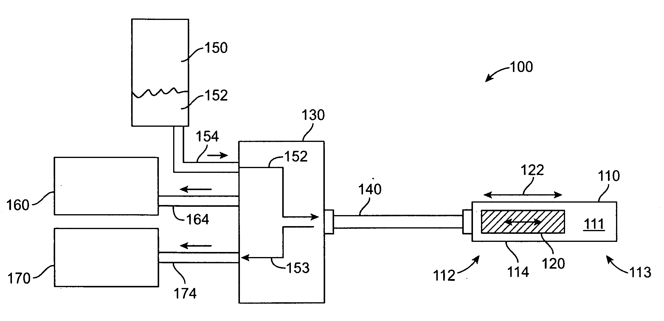
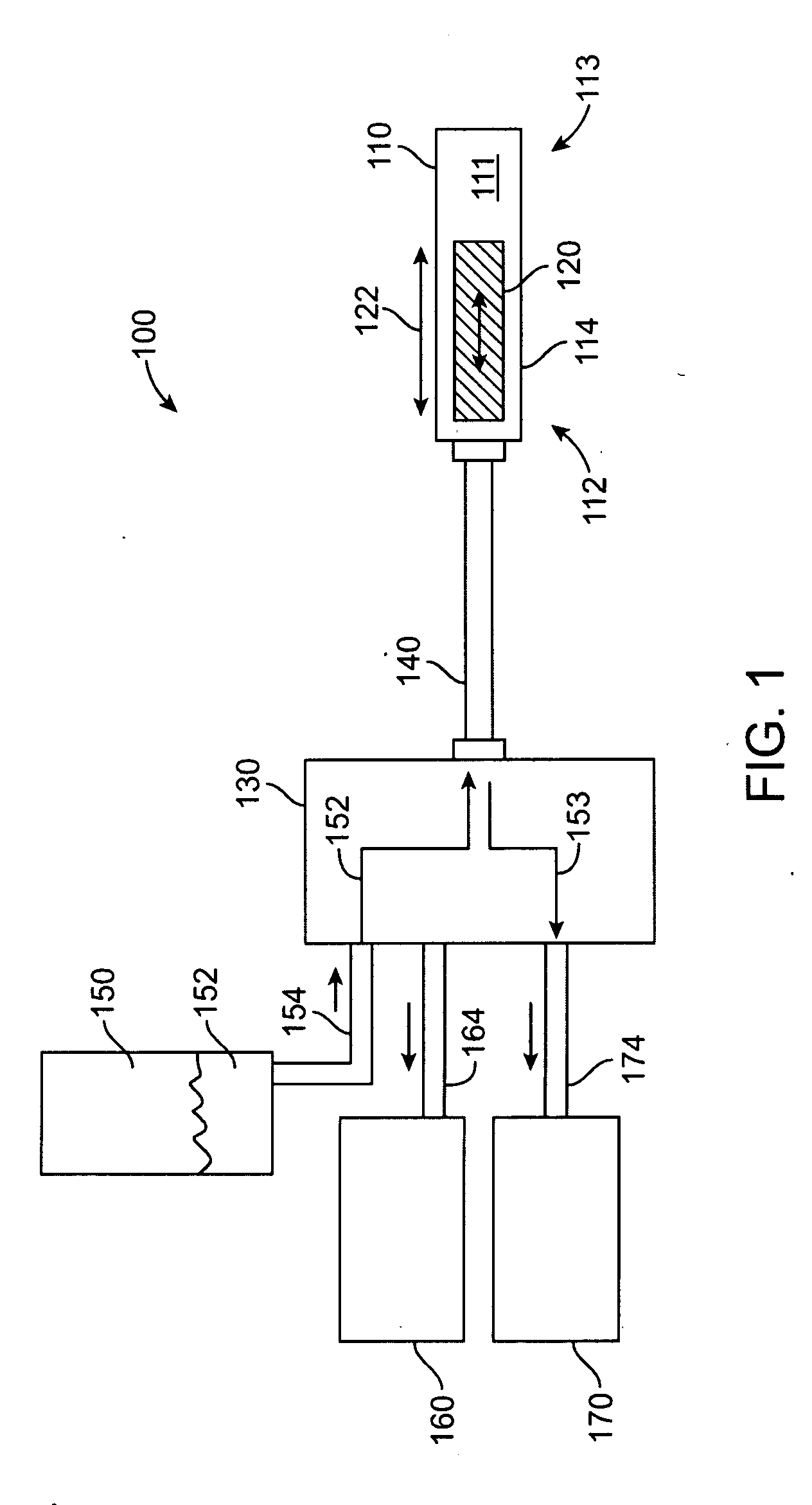
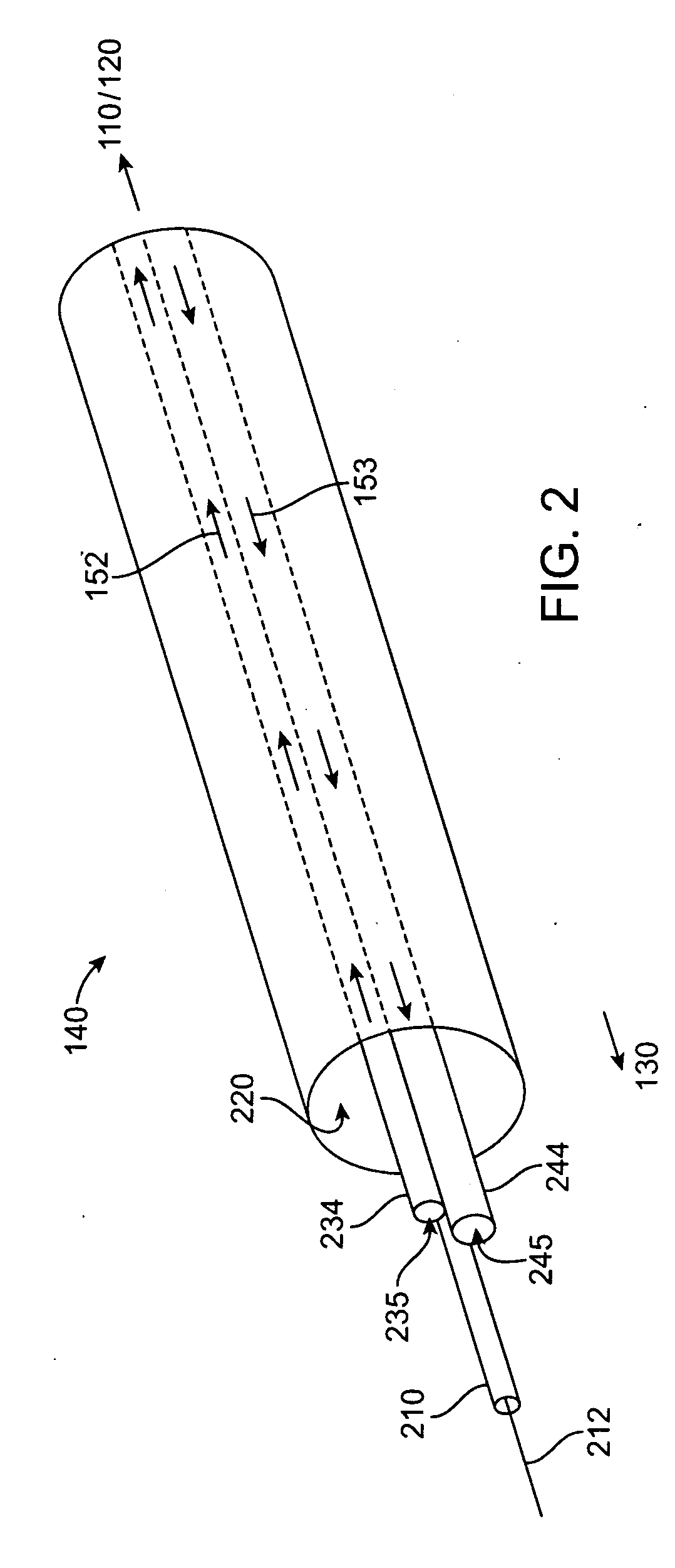
[0043]Embodiments provide systems, apparatus and methods for use in cryogenically ablating tissue, e.g., endocardial tissue. In certain embodiments, a cryogenic ablation device includes an adjustable cooling assembly that can be used to change the shape and / or size or length of a cryogenic ablation region. In certain other embodiments, a balloon ablation device includes a helical or spiral shape, and the adjustable cooling assembly may be integrated within the helical balloon. In certain other embodiments, a cryogenic ablation device is a balloon device and may include multiple balloons, one of which is at least partially wrapped around the other balloon. In certain other embodiments, an adjustable cooling assembly is incorporated into a multi-balloon cryogenic ablation apparatus.

[0044]Further aspects of various embodiments are described with reference to FIGS. 1-21. FIGS. 1-3 illustrate cryogenic ablation systems constructed according to embodiments; FIGS. 4-11 illustrate aspects o...


PUM


Abstract

Apparatus and methods for performing cryogenic ablation of tissue and adjusting the size and/or location of a cryogenic cooling region. A cooling assembly may include tubes for dispensing and exhausting a coolant or refrigerant. One or both of the tubes may be moved, e.g., slidably adjusted, in order to adjust the location or size of a cryogenic ablation region. The cooling assembly may be integrated into cryogenic ablation devices including a cryogenic balloon device that includes an inner inflatable balloon and another balloon that is at least partially wrapped around the inner balloon and carries refrigerant for performing cryo-ablation. Electrodes permit electrical mapping of tissue before or after cryo-ablation to verify success of the procedure.

Description

RELATED APPLICATION DATA[0001]The present application claims the benefit under 35 U.S.C. §119 to U.S. provisional patent application No. 61 / 053,590, filed May 15, 2008. The foregoing application is hereby incorporated by reference into the present application in its entirety.FIELD OF THE INVENTION[0002]The present inventions relate to apparatus, systems and methods for cryogenically ablating tissue such as cardiac tissue.BACKGROUND[0003]Cardiac arrhythmias are a significant health problem, and atrial fibrillation is a common cardiac arrhythmia that may increase risk factors for other conditions such as embolisms and contribute to the onset of ventricular arrhythmia. It is believed that atrial fibrillation is caused by certain electrical signals within the heart. It is believed that cardiac electrical impulses start in a sinoatrial (SA) node, spread through the atria, and progress through the atrial-ventricular (AV) node to the ventricles to complete a heartbeat. Atrial fibrillation ...

Claims


Application Information

Patent Timeline
IPC IPC(8): A61B18/02
CPCA61B18/02A61B2017/22051A61B2017/22054A61M25/1011A61B2018/0022A61B2018/0212A61B2018/0262A61B2018/00196
Inventor INGLE, FRANK W.BENCINI, ROBERT F.KOBLISH, JOSEF V.WOHLGEMUTH, JONATHAN A.ROCHE, PAUL
Owner BOSTON SCI SCIMED INC
Why Eureka
Try Eureka