
Apparatus and program for finding vehicle position

a technology for vehicles and programs, applied in the field of navigation apparatuses, can solve the problems of increasing the calculation load, increasing the memory resource, increasing the cost of the navigation apparatus, etc., and reducing the required calculation load of position finding

Active Publication Date: 2009-11-19
DENSO CORP
View PDF9 Cites 47 Cited by
  • Summary
  • Abstract
  • Description
  • Claims
  • Application Information

AI Technical Summary

Benefits of technology

[0011]In view of the above and other problems, the present disclosure provides an apparatus for finding the current vehicle position on the road links in an accurate manner while reducing the required calculation load of position finding.
[0013]Based on the evaluation of the road links according to the distance between the estimated position and the center locus of the travelable area, the apparatus finds the position of the vehicle. Therefore, the position of the vehicle can be more accurately found and determined. This is because that the center locus of the travelable area is closer to the actual trace of the vehicle travel on the road relative to the road links. Further, the memory area for storing the coordinates of the two-dimensional polygon template is not required, thereby leading to the reduced cost of hardware resources and leading to the reduced number of calculation and processing load in the position finding.

Problems solved by technology

However, a portion of the series of road links diverts from the actual road shape and the actual travel locus, the correlation between the road links and the travel locus is deteriorated, thereby leading to a false positioning by the navigation apparatus, which either concludes that the vehicle is not traveling on the road, or that the travel of the vehicle is associated with other road links such as AF to FC.
The above-described problems are caused by approximating the actual road having an area and a width, that is, a two-dimensional surface by using the one-dimensional elements, i.e., road links.
This leads to the increased memory resources and thus leads to the cost increase of the navigation apparatus.
Further, the increase of the calculation load deteriorates the real-timeness of the navigation, and affects other processing performed in the same CPU.

Method used


Image

  • Apparatus and program for finding vehicle position
  • Apparatus and program for finding vehicle position
  • Apparatus and program for finding vehicle position

Examples


Embodiment Construction

[0028]An embodiment of the present disclosure is described with reference to the drawings. However, the present disclosure is not at all bound or limited by the following description of the embodiment, in terms of the scope of the presented idea.

[0029]In addition, the following description assumes a left-side traffic where vehicles generally travel on a left half of the roads. The right-side traffic implemented countries can, thus, adopt the idea of the present disclosure by replacing the left side with the right side of the road in reading and understanding the description.

[0030](Structure of Navigation Apparatus)

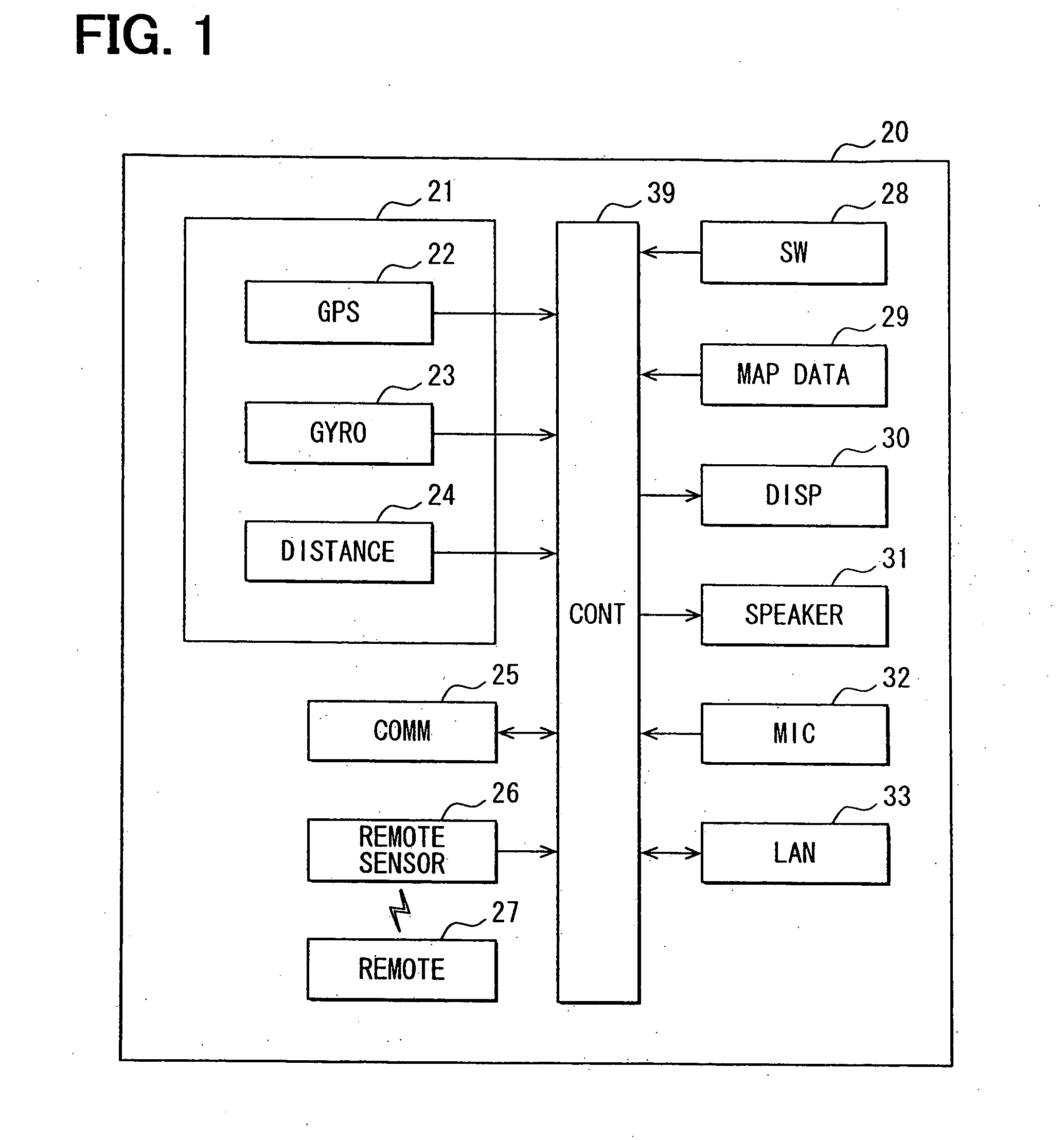
[0031]FIG. 1 is a block diagram showing outline constitution of a navigation apparatus 20 which has a function of a position calculation apparatus of the present disclosure incorporated therein.

[0032]The navigation apparatus 20 is disposed on a vehicle, and includes

[0033]a position detection unit 21 for detecting a current position of the vehicle, a communication unit 25 f...


PUM


Abstract

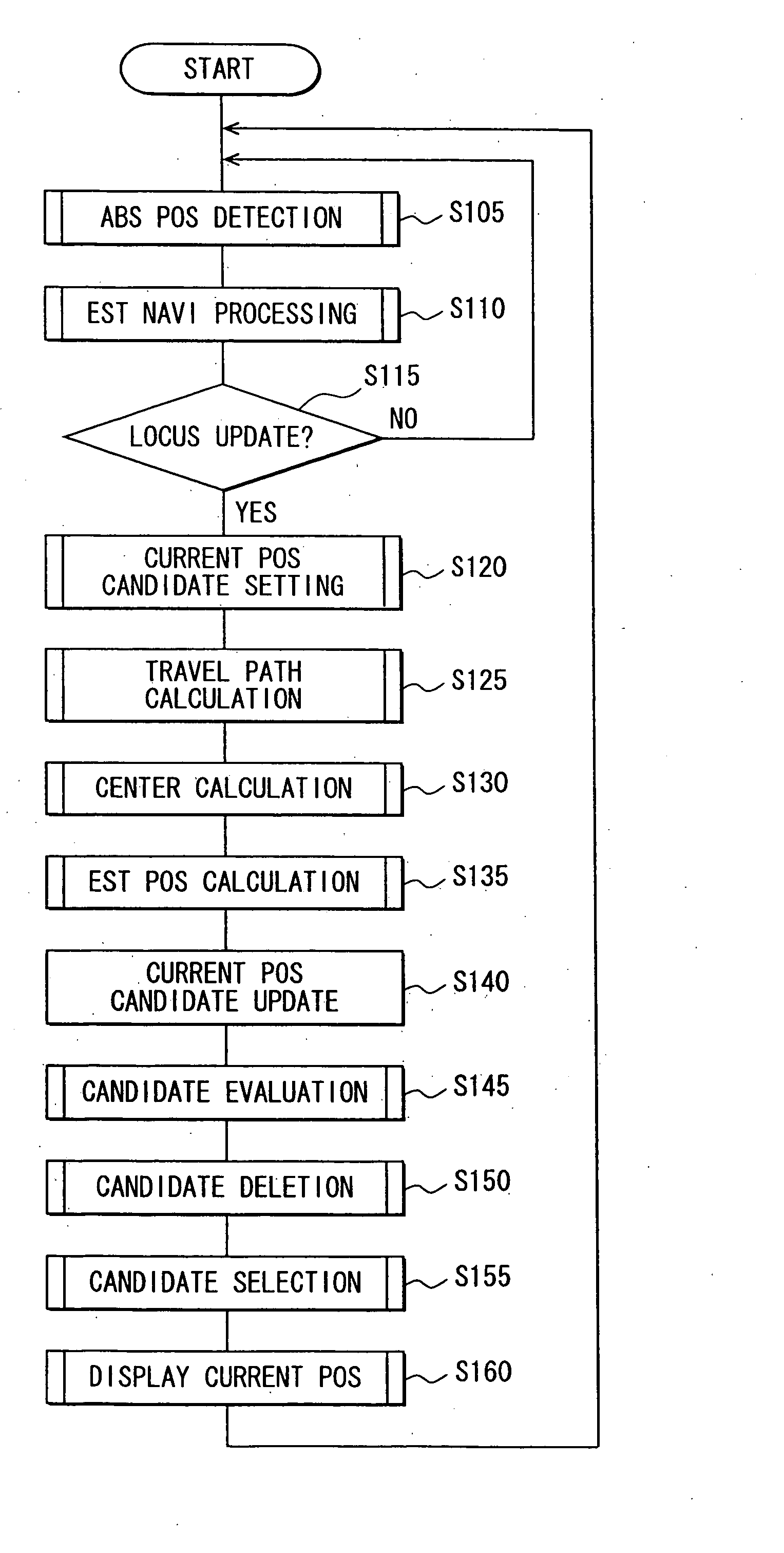
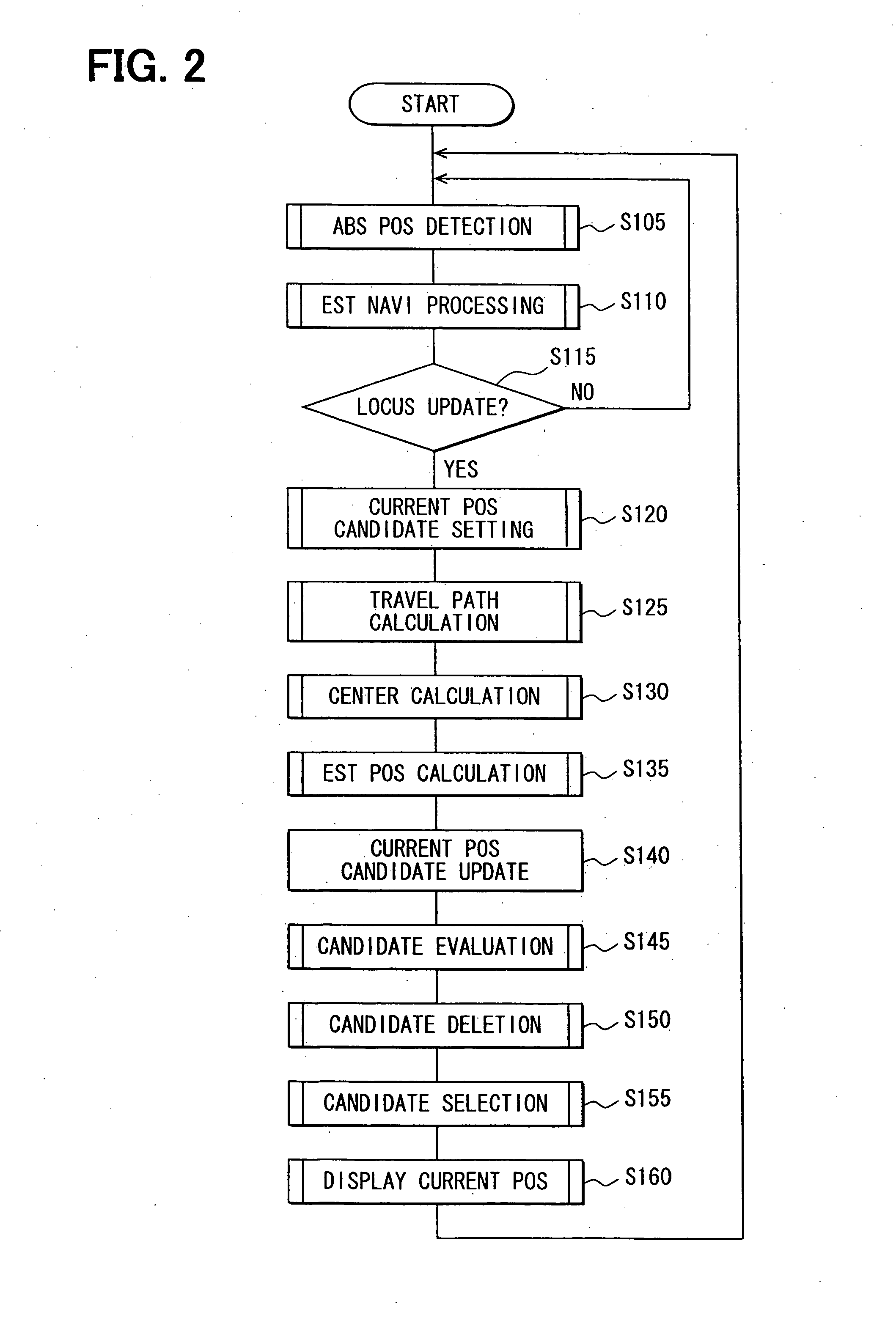
A navigation apparatus calculates a current position candidate of a vehicle based on absolute position information, and calculates a travelable area based on road width data and the like, and further calculates a center locus of the travelable area and an estimated position of the vehicle. The estimated position of the vehicle is then evaluated based on a distance between the estimated position and the center locus to yield a position candidate evaluation for displaying a current position mark on a displayed map.

Description

CROSS REFERENCE TO RELATED APPLICATION[0001]The present application is based on and claims the benefit of priority of Japanese Patent Application No. 2008-128294, filed on May 15, 2008, the disclosure of which is incorporated herein by reference.FIELD OF THE INVENTION[0002]The present disclosure generally relates to a navigation apparatus for use in a vehicle.BACKGROUND INFORMATION[0003]Conventionally, the map matching method used in the navigation apparatus typically finds the vehicle position based on the travel locus of the vehicle calculated by performing the autonomous navigation and by associating the travel locus to the map data. For example, the technique disclosed in a Japanese patent document JP-A-H02-130415 approximates the travel locus of the vehicle by using a fixed length element, and matches the approximation with the map data by selecting, from among the road candidates, one that minimizes the difference of two vectors respectively representing the approximated eleme...

Claims


Application Information

Patent Timeline
Patent Type & Authority Applications(United States)
IPC IPC(8): G01C21/36
CPCG01C21/30
Inventor KOBAYASHI, TOMOKAZU
Owner DENSO CORP
Learn More