Method and system for azimuth measurements using gyro sensors

a technology of gyro sensors and azimuth measurements, applied in the field of azimuth measurement using gyro sensors, can solve the problem that the scale factor of some gyro sensors may be temperature sensitiv

Active Publication Date: 2009-11-19
SCHLUMBERGER TECH CORP
View PDF9 Cites 46 Cited by
  • Summary
  • Abstract
  • Description
  • Claims
  • Application Information

AI Technical Summary

Benefits of technology

[0005]In consequence of the background discussed above, and other factors that are known in the field of oil exploration and development, methods and systems for azimuth measurements using gyro sensors in downhole are provided. In one aspect of the present invention, a method for azimuth measurements using a gyro sensor is provided. The method comprises acquiring a first data from the gyro sensor with an input axis aligned to a first angular orientation parallel to a horizontal plane perpendicular to a gravity direction at a measuring position in downhole; acquiring a second data from the gyro sensor with the input axis flipped to a second angular orientation opposite to the first angular orientation at the measuring point after acquiring the first data; and determining an earth rate component at the first angular orientation based on a difference between the first data and the second data to cancel out bias of the gyro sensor.

Problems solved by technology

Further, scale factor of some gyro sensors may be temperature sensitive.

Method used


Image

  • Method and system for azimuth measurements using gyro sensors
  • Method and system for azimuth measurements using gyro sensors
  • Method and system for azimuth measurements using gyro sensors

Examples


Embodiment Construction

[0033]Illustrative embodiments and aspects of the present disclosure are described below. In the interest of clarity, not all features of an actual implementation are described in the specification. It will of course be appreciated that in the development of any such actual embodiment, numerous implementation-specific decisions must be made to achieve the developers' specific goals, such as compliance with system-related and business-related constraints, that will vary from one implementation to another. Moreover, it will be appreciated that such development effort might be complex and time-consuming, but would nevertheless be a routine undertaking for those of ordinary skill in the art having benefit of the disclosure herein.

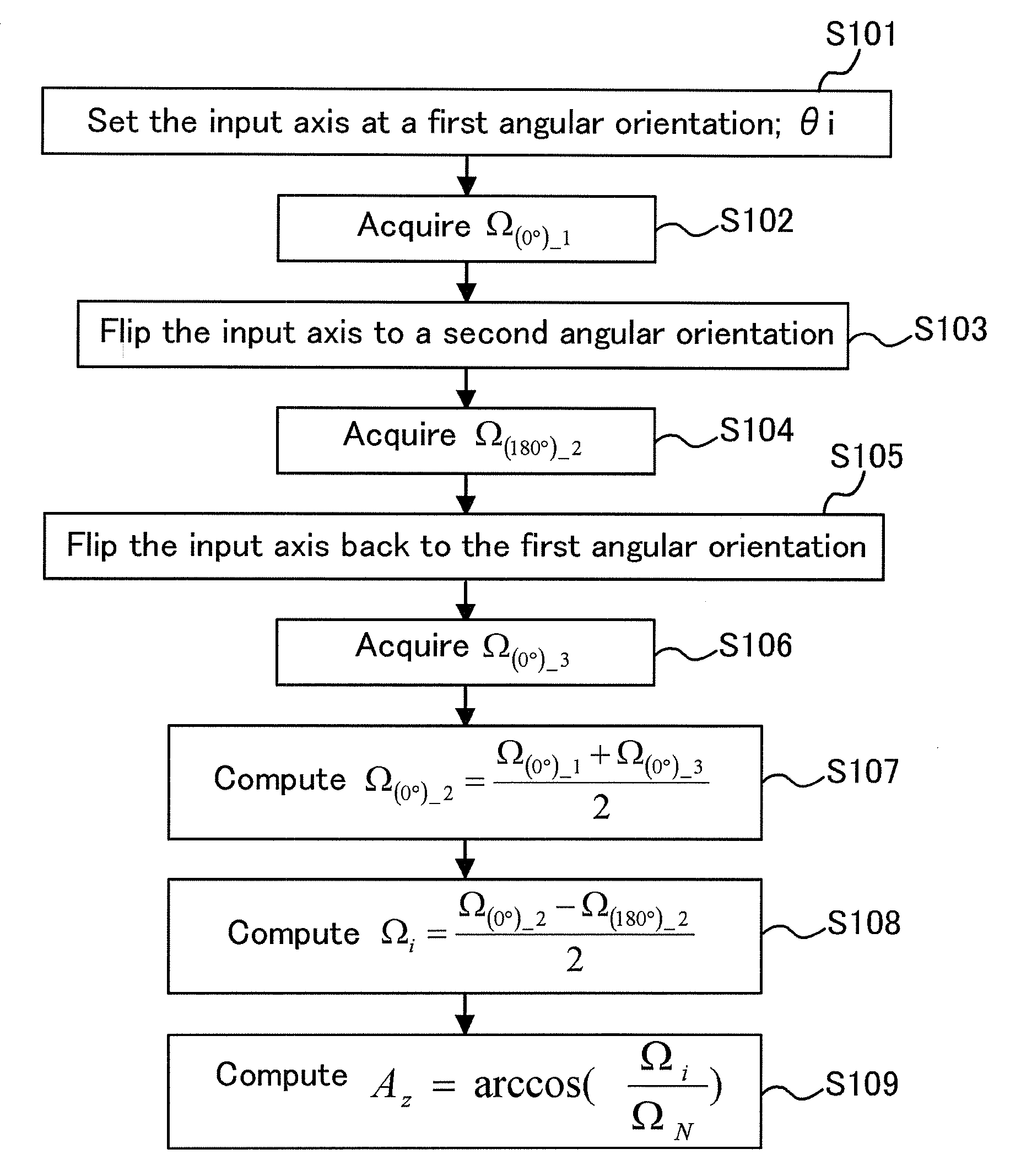
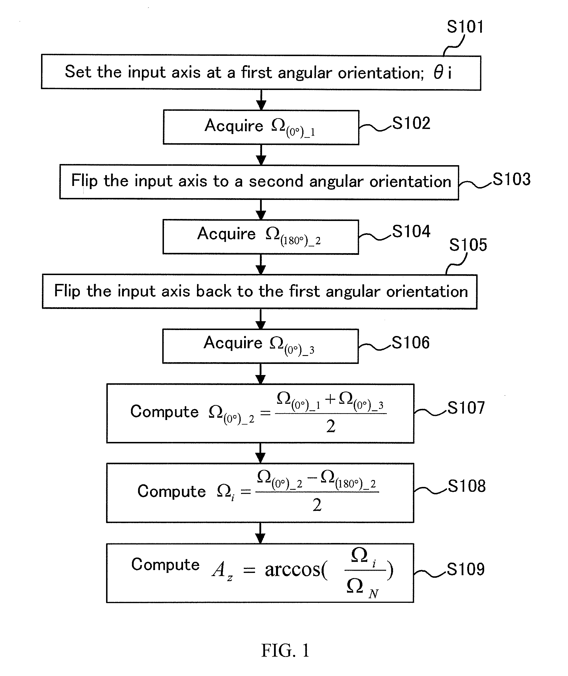
[0034]FIG. 1 shows a flow chart of an embodiment of azimuth measurement methods according to the present invention. In this method, a system for azimuth measurements including one-axis gyro sensor, which can output signals relating to rotation angular rate, is ...


PUM


Abstract

A method and system for azimuth measurements using one or more gyro sensors is disclosed. The method includes acquiring a first data from each of the gyro sensors with an input axis aligned to a first angular orientation and acquiring a second data from each of the gyro sensors with the input axis flipped to a second angular orientation opposite to the first angular orientation. An earth rate component at the first angular orientations is determined based on a difference between the first data and the second data to cancel out bias of each of the gyro sensors. The method may include acquiring a third data of the gyro sensor with the input axis aligned to the same angular orientation as the first angular orientation. An average of the first data and the third data may be used instead of the first data for determining the earth rate component.

Description

CROSS-REFERENCE TO RELATED APPLICATIONS[0001]This application claims priority to U.S. Provisional Patent Application No. 61 / 053,646 filed May 15, 2008, which is incorporated herein by reference.FIELD OF THE INVENTION[0002]The present invention relates to techniques of azimuth measurements using gyro sensors in downhole, for example, for azimuth measurements during Measurement-While-Drilling (MWD) or Logging-While-Drilling (LWD), and wireline logging operations. More particularly, the invention relates to measurements of the earth rate vector direction for azimuth determination with gyros sensors (e.g. MEMS gyro sensors) and accelerometer sensors.BACKGROUND OF THE INVENTION[0003]Azimuth measurement technology in downhole is mostly categorized into measurements with magnetometers and measurements with gyro sensors. The former uses triad magnetometers to measure earth magnet field. However, the magnetometers can be used only in the place without any magnetic influence by magnetic mater...

Claims


Application Information

Patent Timeline
Patent Type & Authority Applications(United States)
IPC IPC(8): G01C9/00G06F15/00
CPCG01C19/42E21B47/022
Inventor SATO, SHIGERUIGARASHI, JUEIKAMIYA, AKIRAYAMATE, TSUTOMU
Owner SCHLUMBERGER TECH CORP
Why Eureka
Try Eureka