Rack for a test cell

a test cell and rack technology, applied in the field of racks for test cells, can solve the problems of not meeting the high requirements of a test cell regarding ease of operation, the line arrangement often does not comply with safety standards, etc., and achieves the effects of simple and quick, high rigidity, and flexible interior spa

Active Publication Date: 2009-11-26
HAWA GMBH & CO KG
View PDF30 Cites 24 Cited by
  • Summary
  • Abstract
  • Description
  • Claims
  • Application Information

AI Technical Summary

Benefits of technology

[0012]Expediently, the box sections that are open towards the outside are accessible from the outside of the rack, and the rear walls of the profile elements and / or the box elements face the interior of the rack. It is an advantage that the open box sections can be made in a simple way, and therefore economically, by bending sheet metal, for example. The end plates that turn the profile elements into box elements act like ribs, giving the box elements a high rigidity. At the same time, the open profile design makes it possible to install lines, for example for the electrical power supply or for conveying gaseous or liquid media, in the vertical and horizontal box sections or box elements. The installation is simple and quick, the arrangement of the lines can be altered at any time, and the lines are protected and arranged in an orderly fashion.
[0013]Preferably, at their end plates and their rear walls facing the interior of the rack, the box elements have passages for the lines to be installed. In addition, in a preferred implementation, and at the attachment points for the box elements, the vertical posts have passages for the lines that are associated with the passages in the end plates of the box elements. This makes it possible to run the lines from the posts through the passages of the posts and the passages in the end plates of the box elements that, as crossbars, connect the posts to form a rack, and from there through passages in the rear walls of the box elements into the interior of the rack, without exiting from the rack towards the outside at any point. Even at the joints of the rack where the crossbars meet the posts, the lines run inside the profile elements through the passages and do not exit from them.
[0014]In an embodiment of the invention, the posts and / or the box elements has standard lengths. This makes a modular and economic construction of the rack of the test cell possible. Due to the various standard lengths, the size of the interior space of the rack can be varied. Said standard lengths may comply with the industrial standards for the dimensions of housings for electrical devices. It also offers advantages if the width and depth dimensions of the posts and crossbars are standardized as well. The standardization of the components for the manufacture of the rack permits its economic mass production and stocking of the parts which shortens the time until the rack is available. A variable construction of the rack in different sizes to meet different requirements is nevertheless possible. In addition, the modular design also permits a later change of the interior space of the rack of an existing test cell.
[0018]For closing the box sections of the posts and of the crossbars that are open towards the outside, covers such as those commonly used for cable channels may be provided in the rack according to the invention. The covers protect the lines installed in the rack and improve the appearance of the test cell.

Problems solved by technology

Such line arrangements often do not comply with safety standards and, above all, no longer meet the high requirements for a test cell regarding the ease of its operation and its overall aesthetic appearance.

Method used


Image

  • Rack for a test cell
  • Rack for a test cell
  • Rack for a test cell

Examples


Embodiment Construction

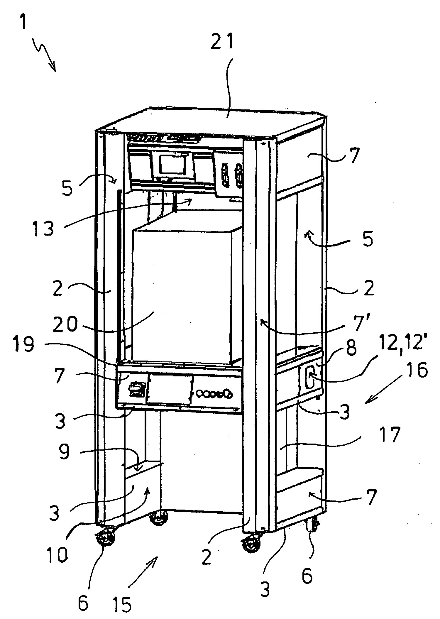
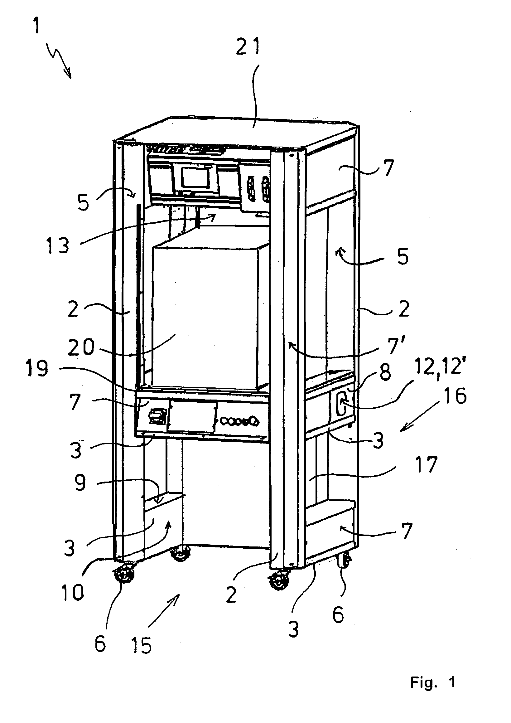
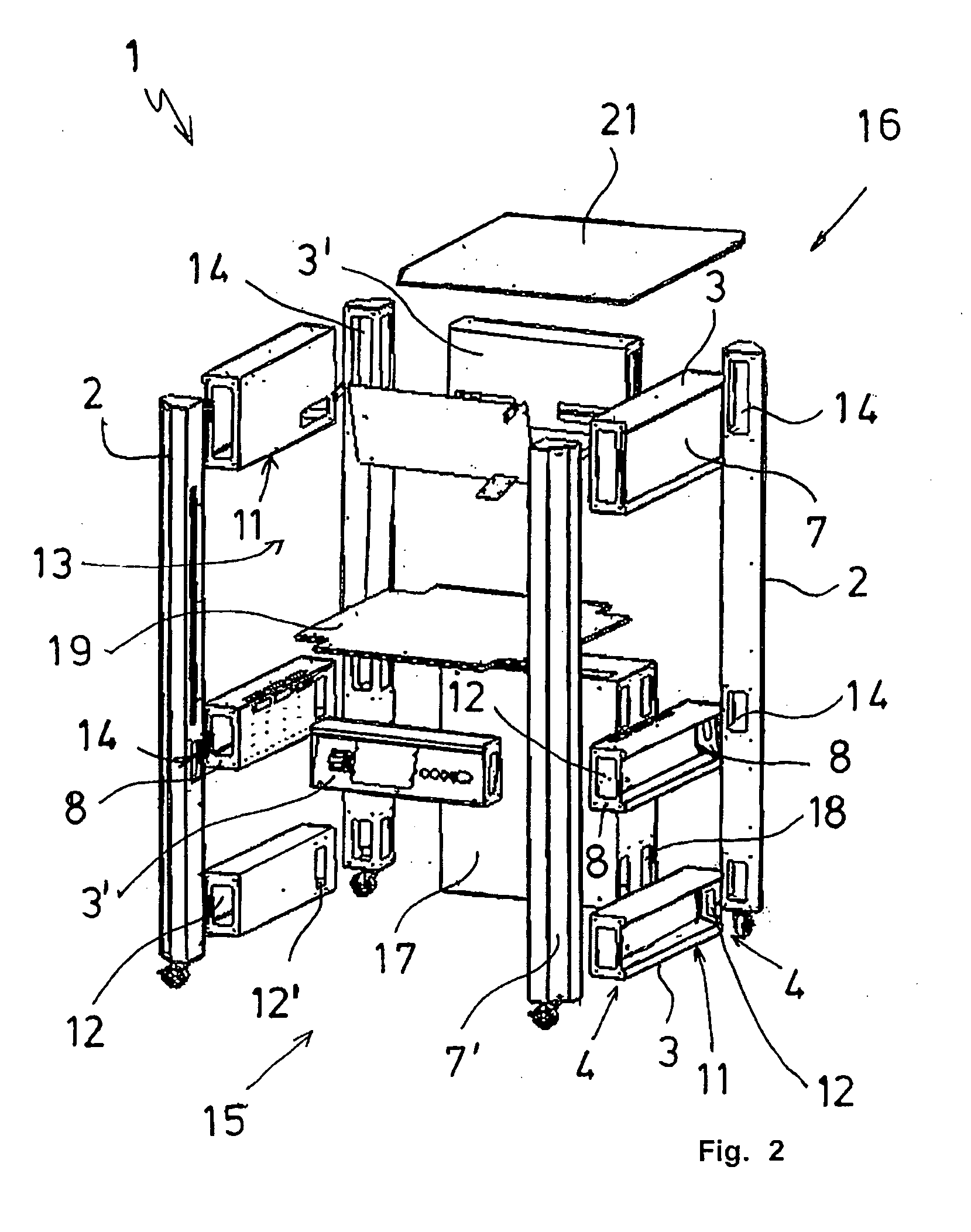
[0022]The rack 1 according to the invention for a test cell shown in FIGS. 1, 2 comprises four vertical posts 2 as corner posts and one or several crossbars 3, 3′ on each side that are located between the corner posts 2. At their ends 4, the crossbars 3, 3′ are connected non-permanently with side walls 5 of the corner posts 2 by means of bolts and nuts (not shown). The rack 1 is supported by rollers mounted at the bottom of the corner posts 2. The corner posts 2 and the crossbars 3, 3′ consist of box sections that are open towards the outside, forming cable channels, and are closed by means of removable covers 7, 7′.

[0023]The corner posts 2 and the crossbars 3, 3′ are structural components of a modular system. For this purpose, the dimensions of the posts 2 and of the crossbars 3, 3′ as well as the associated covers 7, 7′ are standardized. Their standard lengths are based on standardized dimensions for common industrial housing sizes of electrical devices.

[0024]At their ends, the bo...


PUM


Abstract

A rack for a test cell, with vertical posts and horizontal crossbars, wherein the crossbars are connected with their end sections to the posts. The posts and the crossbars have the form of box sections that are open towards the outside, are arranged in a spatial grid, and are connected with each other. The posts as well as the crossbars have passages that are associated with each other and that serve as passages for lines that are installed in the rack.

Description

CROSS-REFERENCE TO RELATED APPLICATION [0001]The present application claims priority under 35 USC §119 to European Patent Application No. 08 009 356.0, filed on May 21, 2008, the entire disclosure of which is incorporated herein by reference.TECHNICAL FIELD OF THE INVENTION [0002]The invention concerns a rack for a test cell with vertical posts and horizontal crossbars, wherein the crossbars are connected with their end sections to the posts. Test cells are also often commonly referred to as test stands and include at least one testing apparatus, technical supply devices, and frequently also integrated instruments. The technical supply devices, the testing apparatus, and the instruments are interconnected with electrical, pneumatic and / or hydraulic lines; the electrical lines may include voltage supply, control, and sensor lines.DESCRIPTION OF THE RELATED ART [0003]In the field, racks are widely used for carrying testing devices. Such racks usually comprise at least four vertical po...

Claims


Application Information

Patent Timeline
Patent Type & Authority Applications(United States)
IPC IPC(8): A47F7/00
CPCH02B1/01H05K7/18H02B1/013
Inventor WURMHORINGER, KLAUS
Owner HAWA GMBH & CO KG
Why Eureka
Try Eureka