Work Positioning Device

a positioning device and positioning pin technology, applied in the direction of work holders, metal-working machine components, manufacturing tools, etc., can solve the problems of long man-hours, high cost, complex forward and backward motion of the positioning pin to be used, etc., and achieve positive positioning, good operability, desirable attractive force

Inactive Publication Date: 2009-11-26
HONDA MOTOR CO LTD
View PDF6 Cites 3 Cited by
  • Summary
  • Abstract
  • Description
  • Claims
  • Application Information

AI Technical Summary

Benefits of technology

[0013]According to the third aspect of the present invention, the positioning pin can be positively fixed because the positioning pin is gripped with the outer circumferential surface of the columnar body, and the workpiece can be positively positioned because the workpiece can be magnetically attracted.
[0014]According to the fourth aspect of the present inven

Problems solved by technology

In the fixed type positioning pin, work such as bolt removal and fastening occurs on the occasion of replacement, posing the problem that man-hours are long.
In the multi

Method used


Image

  • Work Positioning Device
  • Work Positioning Device
  • Work Positioning Device

Examples


Embodiment Construction

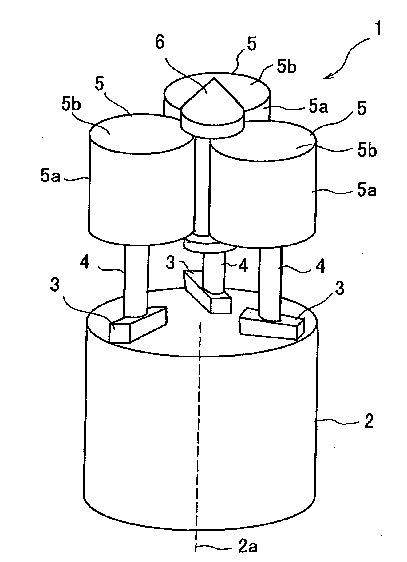
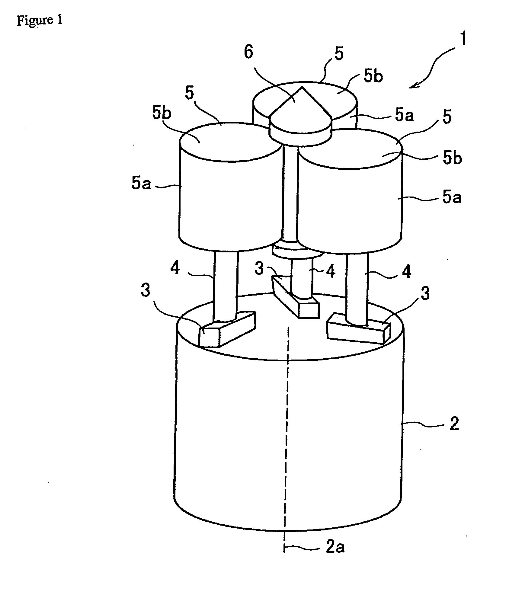
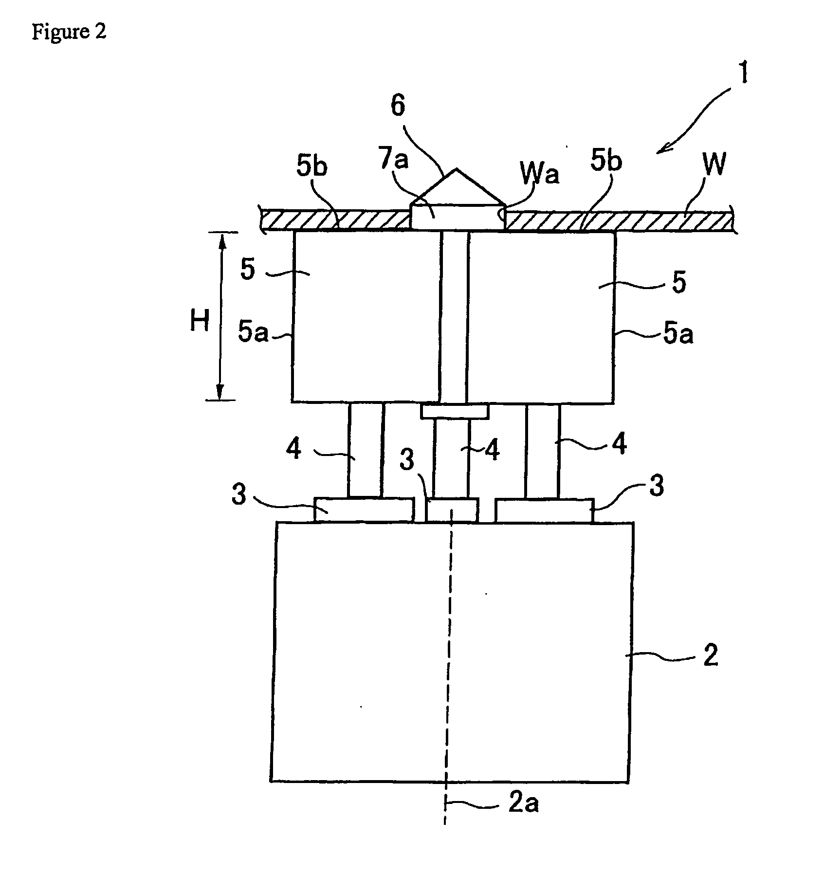
[0021]An embodiment of the present invention will be described below on the basis of the accompanying drawings. FIG. 1 is a general perspective view of a workpiece positioning device related to the present invention. FIG. 2 is a general side view of the workpiece positioning device. FIG. 3 is a general plan view of the workpiece positioning device. FIG. 4 is a side view of a positioning pin. FIGS. 5(a), 5(b) and 5(c) are diagrams to describe the operation of the workpiece positioning device.

[0022]As shown in FIGS. 1 to 3, the workpiece positioning device 1 related to the present invention comprises a chuck driving portion 2 in the shape of a cylindrical column, which is provided in a jig (not shown), three sliding members 3 that move forward and backward on a top surface of the chuck driving portion 2 radially from a central axis 2a of the chuck driving portion 2 at intervals of 120° in central angle, three locking members 5 that are attached to each of the three sliding members 3 e...


PUM


Abstract

Provided is a workpiece positioning device that facilitates the replacement work of a positioning pin and does not require a mechanical mechanism for clamping a workpiece. This is a workpiece positioning device that positions a workpiece (W) by inserting a positioning pin (6) into a positioning hole (Wa) of the workpiece (W), wherein the workpiece positioning device comprises three locking members (5) that grip the positioning pin (6) in a protruding condition, and exert a magnetic attractive force, and three sliding members (3) that move each of the three locking members (5) forward and backward radially with respect to the positioning pin (6). The locking member (5) is formed in the shape of a cylindrical column, and grips the positioning pin (6) with an outer circumferential surface (5a) thereof and magnetically attracts the workpiece (W) with a top surface (5a) thereof. The magnetic attractive force of the locking member (5) is adjusted by excitation means.

Description

TECHNICAL FIELD[0001]The present invention relates to a workpiece positioning device that is used to position a plate-like workpiece in a jig.BACKGROUND ART[0002]As a device that positions a plate-like workpiece to be welded in a jig, there has hitherto been known a device which is such that after a fixed positioning pin provided in a standing manner in the jig is inserted into a positioning hole of the workpiece, the workpiece is clamped by use of a clamping mechanism provided in the vicinity of the positioning pin to perform positioning (refer to Patent Document 1, for example).Patent Document 1: Japanese Patent Laid-Open No. 2-179364[0003]However, in the case of a method that involves using such a fixed type positioning pin, when the size and position of the positioning hole of the workpiece change due to a change of the machine type, in general, it is necessary to prepare a new fixed type positioning pin or a multistage type positioning pin suitable for multiple machine types al...

Claims


Application Information

Patent Timeline
IPC IPC(8): B23Q3/15B23Q3/06B25B11/00
CPCB25B11/002B23Q3/183
Inventor NAGATO, TERUAKI
Owner HONDA MOTOR CO LTD
Why Eureka
Try Eureka