
Dynamic Sub-Channel Sizing

a sub-channel and dynamic technology, applied in the field of wireless communications, can solve the problems of limiting the number of customers that may be adequately served, limiting the bandwidth of each subscriber, and the demand for such broadband services continuing to grow

Inactive Publication Date: 2009-11-26
VIASAT INC
View PDF55 Cites 21 Cited by
  • Summary
  • Abstract
  • Description
  • Claims
  • Application Information

AI Technical Summary

Problems solved by technology

While such first generation satellite systems may provide multi-gigabit per second (Gbps) per satellite overall capacity, the design of such systems inherently limits the number of customers that may be adequately served.
Moreover, the fact that the capacity is split across numerous coverage areas further limits the bandwidth to each subscriber.
While existing designs have a number of capacity limitations, the demand for such broadband services continues to grow.

Method used


Image

  • Dynamic Sub-Channel Sizing
  • Dynamic Sub-Channel Sizing
  • Dynamic Sub-Channel Sizing

Examples


Embodiment Construction

[0048]The ensuing description provides preferred exemplary embodiment(s) only, and is not intended to limit the scope, applicability or configuration of the disclosure. Rather, the ensuing description of the preferred exemplary embodiment(s) will provide those skilled in the art with an enabling description for implementing a preferred exemplary embodiment. It is being understood that various changes may be made in the function and arrangement of elements without departing from the spirit and scope as set forth in the appended claims.

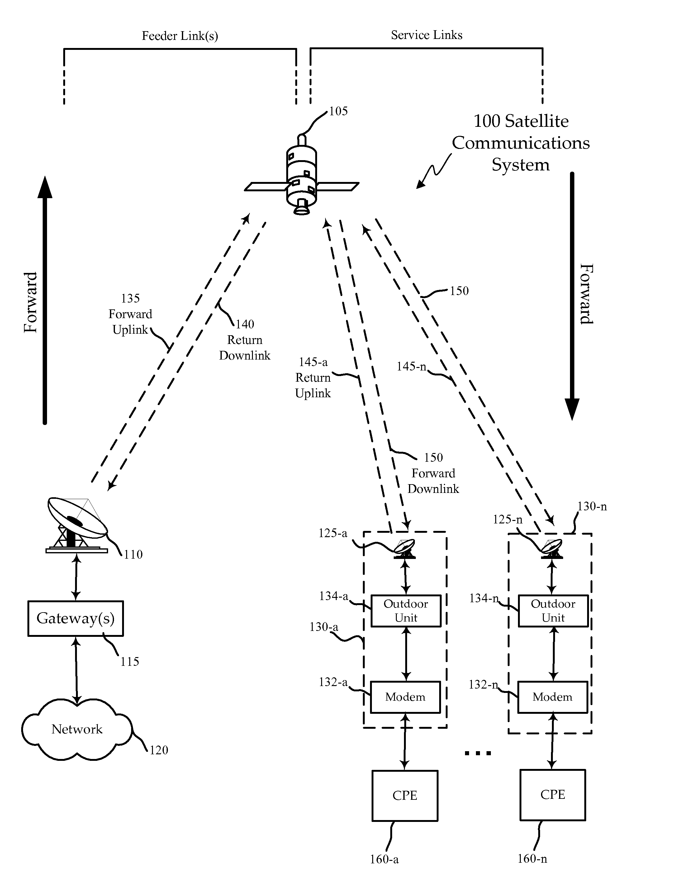
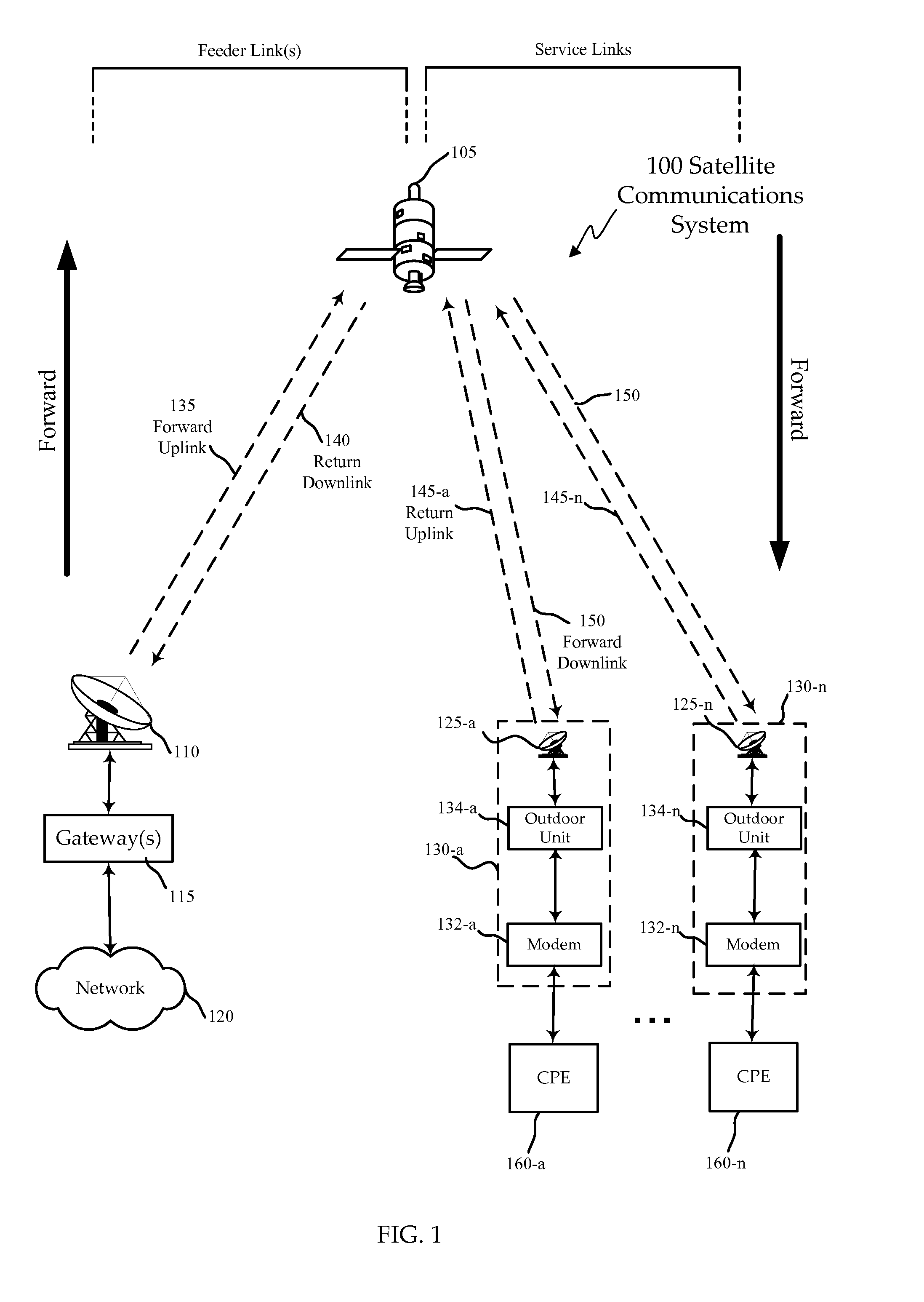
[0049]FIG. 1 is a block diagram of an exemplary satellite communications system 100 configured according to various embodiments of the invention. The satellite communications system 100 includes a network 120, such as the Internet, interfaced with one or more gateways 115 that is configured to communicate with one or more subscriber terminals 130, via a satellite 105. The gateway 115 is sometimes referred to as a hub or ground station. Subscriber termin...


PUM


Abstract

A satellite system for broadband communication with a plurality of remote locations is described. The satellite system comprises service spot beams from a satellite. Forward channels may be transported on carriers of the service spot beams. A plurality of forward sub-channels may pass on the forward channels. They system further comprises a plurality of domains that are independently managed and a plurality of satellite modems with the service spot beams. The plurality of sub-channels may be divided among the plurality of domains. Each of the domains may correspond to a plurality of time slices. A scheduler may allocate forward channels among the plurality of domains. Each of the time slices corresponding to the plurality of domains may vary in size over time.

Description

[0001]This is a continuation of PCT Application No. PCT / US07 / 79577 entitled “Improved Spot Beam Satellite Ground Systems” and filed on Sep. 26, 2007, which is a non-provisional of:[0002]Provisional Application Ser. No. 60 / 828,038 entitled “DOCSIS MAC Chip Adapted” and filed on Oct. 3, 2006 (Attorney Docket No. 017018-009500US);[0003]Provisional Application Ser. No. 60 / 828,046 entitled “Virtual Channel Load Balancing” and filed on Oct. 3, 2006 (Attorney Docket No. 017018-009800US);[0004]Provisional Application Ser. No. 60 / 828,048 entitled “Satellite Upstream / Downstream Virtual Channel Architecture” and filed on Oct. 3, 2006 (Attorney Docket No. 017018-010000US);[0005]Provisional Application Ser. No. 60 / 828,032 entitled “Multi-User Detection in Satellite Return Link” and filed on Oct. 3, 2006 (Attorney Docket No. 017018-010100US);[0006]Provisional Application Ser. No. 60 / 828,034 entitled “Multi-Rate Downstreaming in Multiple Virtual Channel Environment” and filed on Oct. 3, 2006 (Atto...

Claims


Application Information

Patent Timeline
Patent Type & Authority Applications(United States)
IPC IPC(8): H04B7/185
CPCH04B7/2041H04B7/18582
Inventor MCDANIEL, JEFFREY M.
Owner VIASAT INC
Learn More