

Display apparatus and drive method thereof
a technology of display apparatus and drive circuit, which is applied in the direction of electrical discharge tubes, instruments, computing, etc., can solve the problems of flicker, increased power consumption, and increased operating speed of drive circuit, and achieve excellent display and suppress image quality degradation
- Summary
- Abstract
- Description
- Claims
- Application Information
AI Technical Summary
Benefits of technology
Problems solved by technology
Method used
Image

Examples
first embodiment
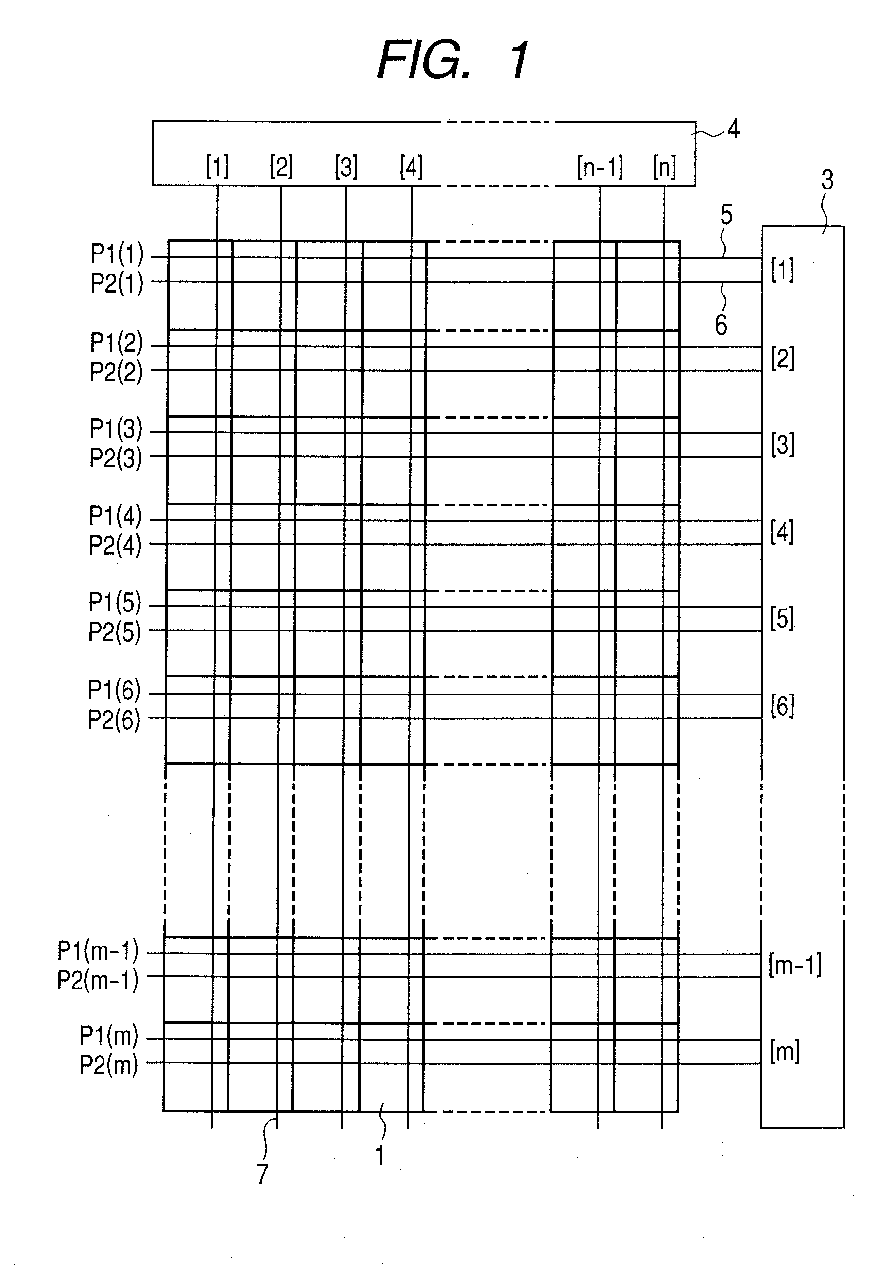
[0085]FIG. 1 illustrates an overall configuration of a display apparatus according to the present invention.
[0086]In FIG. 1, an image display unit is arranged with pixels 1 two-dimensionally in the row and column directions. The number of rows is taken as m and the number of columns is taken as n.
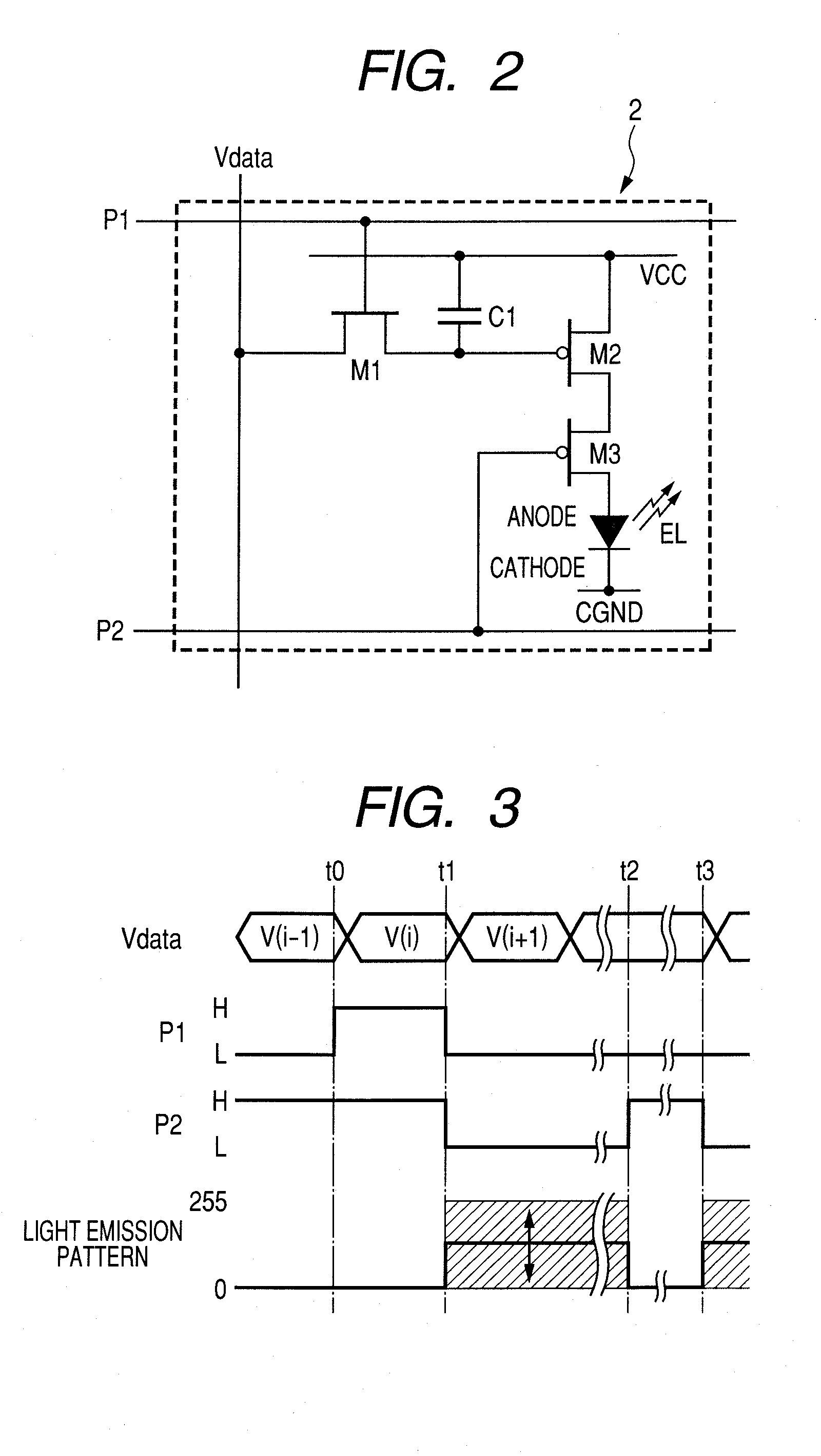
[0087]Each of the pixels 1 includes EL elements of RGB primary colors and pixel circuits 2 (refer to FIG. 2) which are provided to the respective EL elements and control an electric current to be input. The pixel circuit 2 is a circuit including a thin film transistor (TFT).
[0088]Around the image display unit, a row control circuit 3 and a column control circuit 4 are provided. From respective output terminals of the row control circuit 3, scanning lines 5 and control lines 6 for controlling light emission extend to the row direction. Scanning signals P1(1) to P1(m) and light-emission control signals P2(1) to P2(m) are supplied to these scanning lines 5 and control lines 6, respectively. Th...
second embodiment
[0119]The overall configuration of a display apparatus according to the present embodiment is the same as that of FIG. 1. A pixel circuit 2 and a drive method therefor are the same as those of FIGS. 2 and 3 and therefore description and drawings thereof will be omitted.
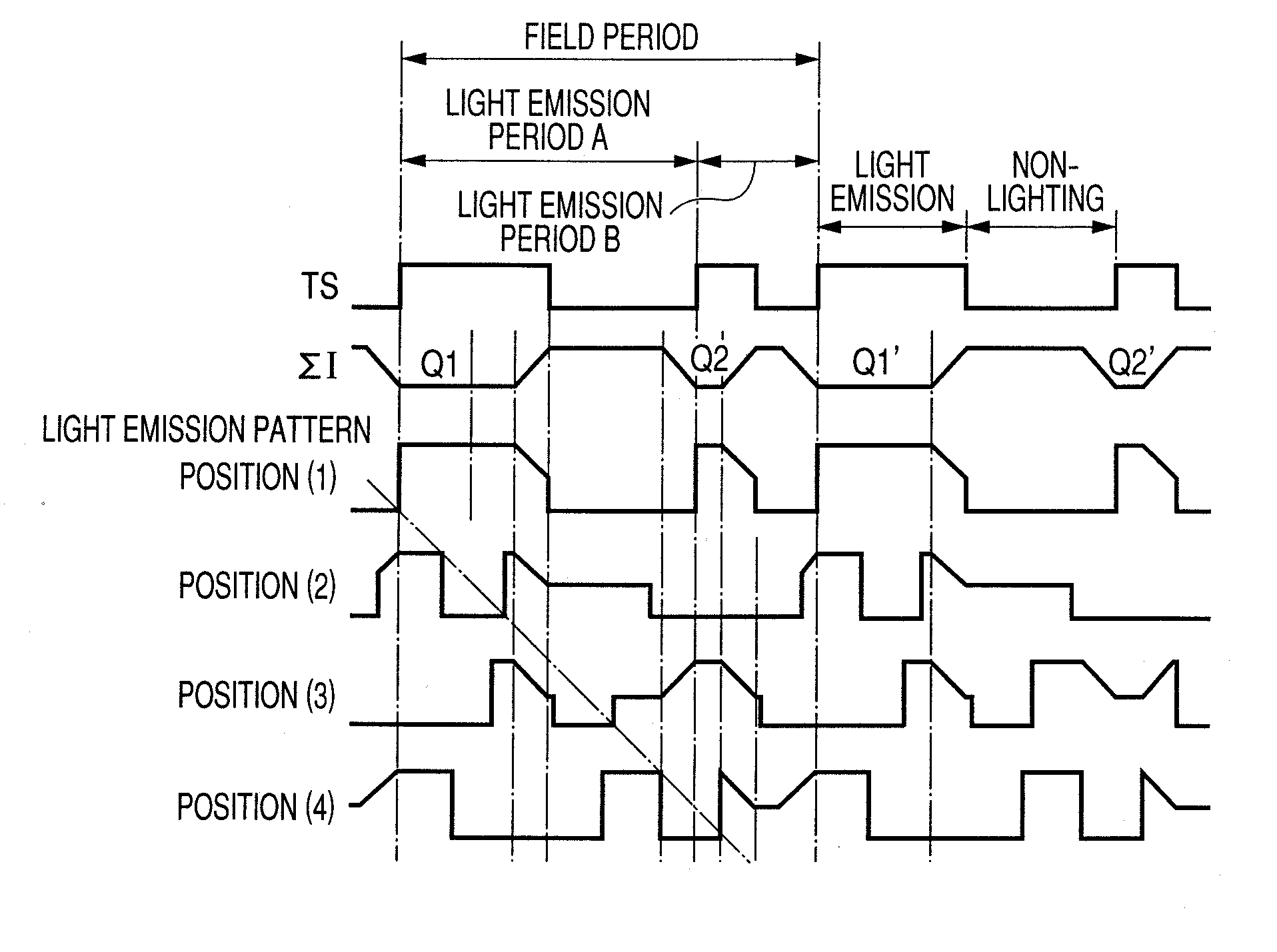
[0120]FIG. 7 is a timing chart illustrating another example of drive method of the display apparatus according to the present invention.
[0121]In FIG. 7, P1(1) to P1(m) show a scanning signal P1 corresponding to each of 1st to m-th rows. P2(1) to P2(m) show a light-emission control signal P2 corresponding to each of 1st to m-th rows. A difference from the drive method described in the timing chart illustrated in FIG. 4 is a waveform of a light-emission control signal P2.
[0122]The light-emission control signal P2 in the present embodiment is set to a waveform for driving at least one light-emission period in a light emission pattern different from other light-emission periods. Otherwise, the light-emission control signa...
third embodiment
[0130]The overall configuration of a display apparatus according to the present embodiment is the same as that of FIG. 1. A pixel circuit 2 and a drive method therefor are the same as those of FIGS. 2 and 3 and an example of a timing chart describing the drive method is the same as those of FIG. 4 and therefore description and drawings thereof will be omitted.
[0131]FIG. 9 illustrates a waveform of a light-emission control signal P2 having a plurality of impulse operation periods in a field period, in which patterns A to E in one of impulse operation periods (impulse operation period C) are changed to be short and pattern F is changed to be long, with a duty ratio being maintained. The lengths of other impulse operation periods change by an amount corresponding to a change in the length of the impulse operation period C. “A” denotes that impulse operation periods are all equal. “C” denotes that an impulse operation period C has an approximately half length as large as other impulse o...
PUM
 Abstract
Description
Claims
Application Information