
Container Comprising A Sealing Element

a technology of sealing element and container, applied in the field of containers, can solve the problems of time-consuming and costly installation, complicated construction, and cost-intensive solutions, and achieve the effect of simple and cost-effective production

Inactive Publication Date: 2009-11-26
CONTINENTAL TEVES AG & CO OHG
View PDF6 Cites 4 Cited by
  • Summary
  • Abstract
  • Description
  • Claims
  • Application Information

AI Technical Summary

Benefits of technology

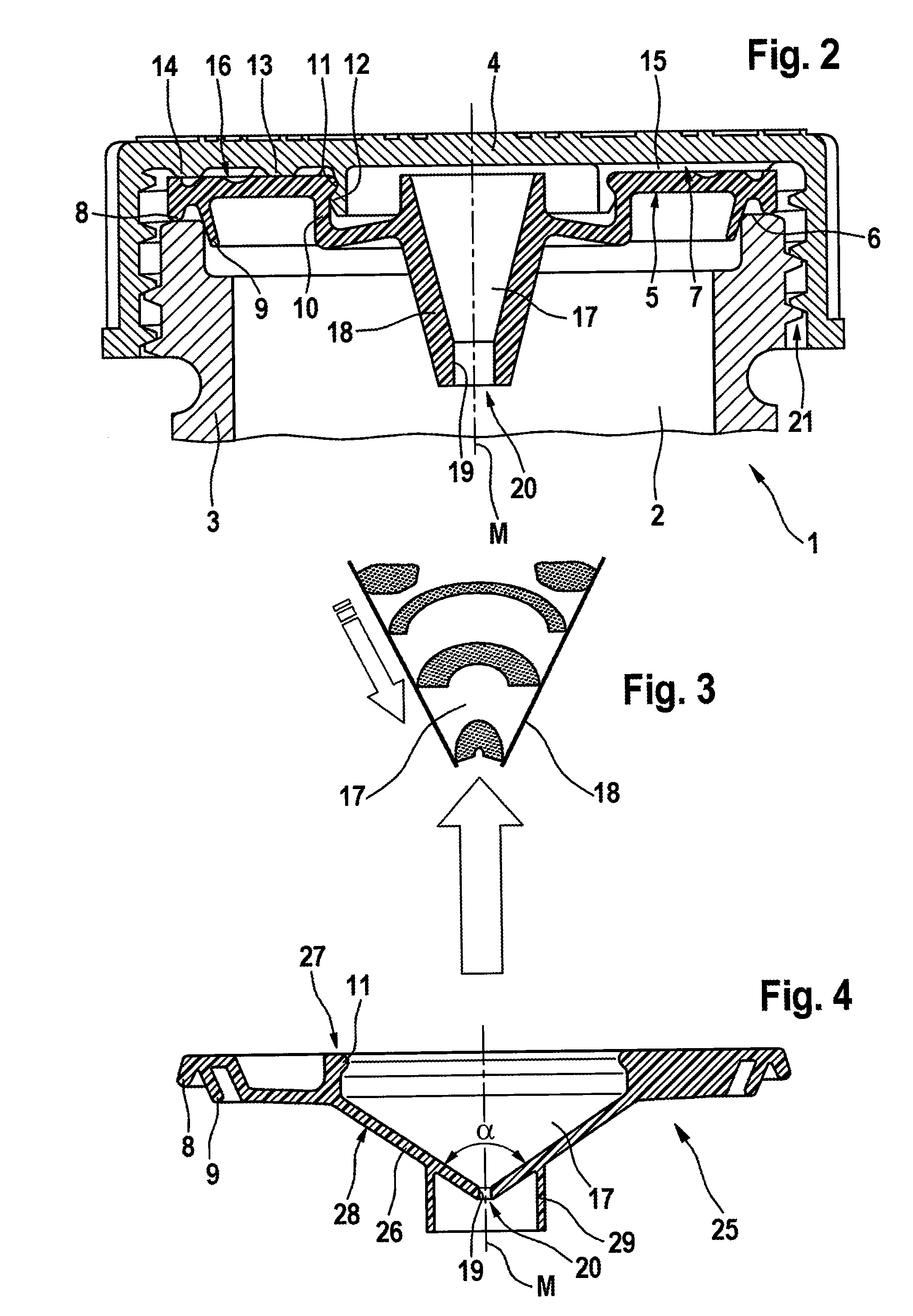
The present invention provides a container with a sealing element that can be produced simply and cost-effectively, with adequate ventilation and aeration. The sealing element has a space that is connected to the atmosphere and has one or more openings facing the chamber, which allows liquid medium to enter the space and be displaced by a gaseous medium. The gaseous medium can then flow into the atmosphere via the sealing element. The container does not require additional sealing components. The sealing element can be fastened to the cover of the container, and the sealing element can be designed in a flat or curved shape. The sealing element can also have openings at its periphery to improve ventilation and aeration during extreme oblique positions of the container. The method of ventilating and aerating the container involves displacing the liquid medium that penetrates the sealing element with a gaseous medium and allowing the medium to be forced back into the chamber when a threshold surface tension is reached.

Problems solved by technology

Drawbacks of the abovementioned containers include the complicated construction and the time-consuming and costly installation.
Furthermore, in the known containers use is frequently made of components and sealing elements which are produced from rubber-like materials or require a high degree of accuracy, which often leads to cost-intensive solutions.

Method used


Image

  • Container Comprising A Sealing Element
  • Container Comprising A Sealing Element
  • Container Comprising A Sealing Element

Examples


Embodiment Construction

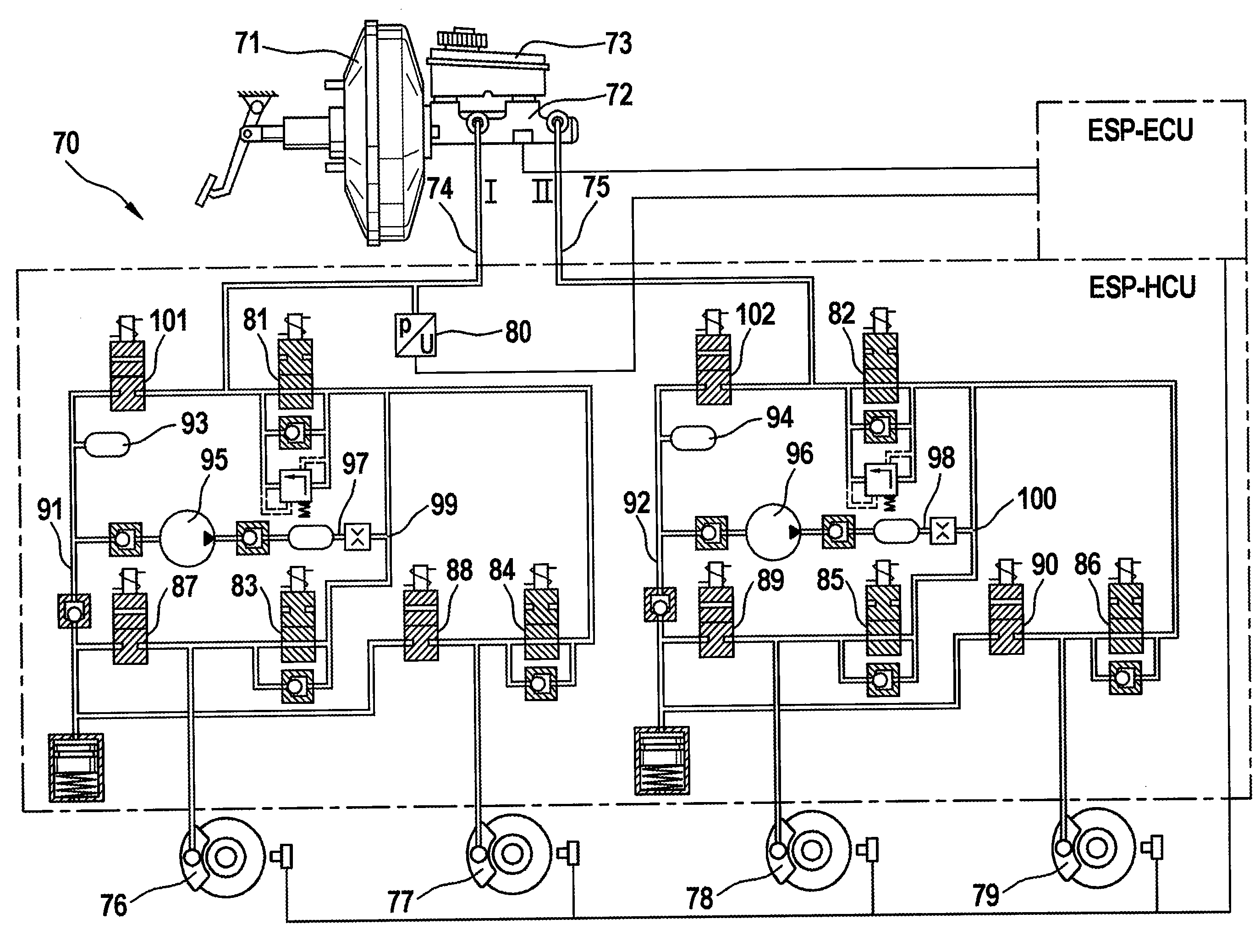
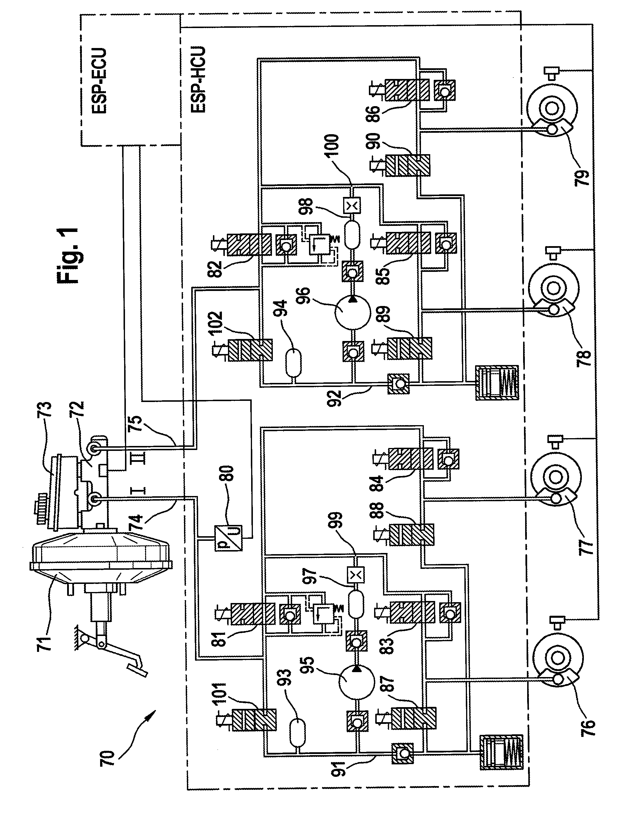
[0032]FIG. 1 serves to explain an electrohydraulic braking system 70 which is known per se, is equipped here by way of example with an electronic stability control system (ESP) and in which use can be made of a container according to aspects of the invention from the exemplary embodiments below.

[0033]In principle, however, the use of the principle according to aspects of the invention is not restricted to a vehicle braking system or in general to automobile construction. A container according to aspects of the invention can conceivably be used in every technical field in which the use of a pressure-equalized container with a liquid medium is required.

[0034]The braking system 70 comprises a brake device with a pneumatic brake booster 71, and a pedal-actuable main cylinder 72 with an unpressurized pressure medium container 73, with pressure spaces (not illustrated) of the main cylinder 72 being connected to wheel brakes 76-79 via brake lines 74, 75. The wheel brakes 76-79 are combined...


PUM


Abstract

A pressure medium container for hydraulic motor vehicle braking systems, with at least one chamber which can be filled with a liquid medium via a filler neck, and with a cover which can be fastened to the filler neck and has means for equalizing the pressure between the chamber and the atmosphere, wherein a sealing element is provided to prevent the liquid medium from emerging from the chamber. The sealing element has a space exposed to the atmosphere and has one or more openings facing the chamber, the space being configured such that liquid medium penetrating the space undergoes an increase in surface area, while its volume remains constant, when displaced by means of a further gaseous medium, and, when a threshold surface tension is reached, the liquid medium is forced back into the chamber such that the gaseous medium can flow into the atmosphere via the sealing element.

Description

CROSS REFERENCE TO RELATED APPLICATIONS[0001]This application is the U.S. national phase application of PCT International Application No. PCT / EP2007 / 054536, filed May 10, 2007, which claims priority to German Patent Application No. DE 10 2006 031 931.1, filed Jul. 11, 2006 and German Patent Application No. DE 10 2006 046 479.6, filed Sep. 29, 2006, the contents of such applications being incorporated by reference herein.BACKGROUND OF THE INVENTION[0002]1. Field of the Invention[0003]The invention relates to a container, in particular to a pressure medium container for hydraulic motor vehicle braking systems, with at least one chamber which can be filled with a liquid medium via a filler neck, and with a cover which can be fastened to the filler neck and has means for equalizing the pressure between the chamber and the atmosphere, wherein a sealing element is provided to prevent the liquid medium from emerging from the chamber.[0004]2. Description of the Related Art[0005]Containers h...

Claims


Application Information

Patent Timeline
Patent Type & Authority Applications(United States)
IPC IPC(8): B65D51/16
CPCB60T8/4872B60T17/06B60T11/22
Inventor NEUMANN, HANS-JURGENSCHIEL, CHRISTOPHSCHLICHT, STEPHAN
Owner CONTINENTAL TEVES AG & CO OHG
Learn More