Flow-Conducting Component

Active Publication Date: 2017-08-03
KSB AG
View PDF5 Cites 1 Cited by
  • Summary
  • Abstract
  • Description
  • Claims
  • Application Information

AI Technical Summary

Benefits of technology

[0011]This simple construction method makes it possible very simply to determine a geometry which in a direction-dependent manner takes into account the differential mechanical load in the component. Impinging forces are analyzed under the effect of the conveyed medium and the operating conditions provided, wherein minimum and maximum values are determined. According to these values the mechanical stability required for the impeller is determined. The method of calculation predetermines the geometric configuration and thus also the use of material and the machining of workpieces.
[0012]In an advantageous embodiment the flow-conducting component is produced by a generative process, wherein in particular metal powders are joined to form a component by a beam melting process such as for example laser or electron beam melting. This has the advantage that the i

Problems solved by technology

At sections which are particularly loaded and above all at the transitions between different sections, in particular mechanical stresses can be built up which lead to shortening of the service lives.
Both casting technology and also joining technology quickly reach the limits for flow-conducting components, since in some instances the notches are access

Method used


Image

  • Flow-Conducting Component
  • Flow-Conducting Component
  • Flow-Conducting Component

Examples


Example

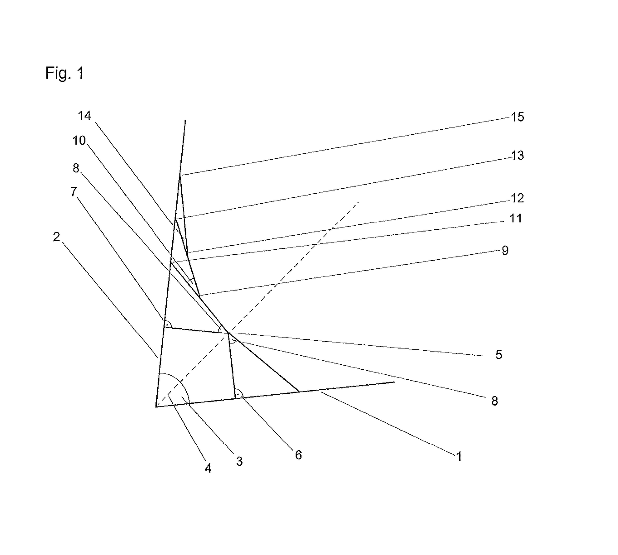
[0019]FIG. 1 shows an arbitrary location at which the contour of a component transitions from a first zone 1 discontinuously into a second zone 2, wherein the two sections enclose an angle 3. At this point of discontinuity considerable stresses develop which can be influenced significantly by a suitably designed geometric configuration. In the case of a predefined breaking point the stresses can be used in order to allow the component to break in a targeted manner at the point of discontinuity under a threshold load. Usually, however, the opposite is desirable, and the point of discontinuity should be sufficiently resilient against the applied forces. A so-called engineer's notch is traditionally provided here which shapes the sharp angle by a curve with a chosen radius.

[0020]With reference to various observations in nature, a method for designing the notch has been developed which is simple to construct and nevertheless absorbs the forces at the point of discontinuity so that the l...


PUM

PropertyMeasurementUnit
Angleaaaaaaaaaa
Angleaaaaaaaaaa
Lengthaaaaaaaaaa

Abstract

A flow-conducting component such as a pump impeller is provided. Passages between vanes of the flow-conducting component include notches in the form of transitions between the vane and a common surface, such as a cover disk. The notches include a transition surface having a geometric configuration determined in accordance with a calculated load spectrum along at least a portion of the length of the notch and in accordance with a particular geometric pattern.

Description

CROSS REFERENCE TO RELATED APPLICATIONS[0001]This application is a National Stage of PCT International Application No. PCT / EP2015 / 067235, filed Jul. 28, 2015, which claims priority under 35 U.S.C. §119 from German Patent Application No. 10 2014 215 089.2, filed Jul. 31, 2014, the entire disclosures of which are herein expressly incorporated by reference.BACKGROUND AND SUMMARY OF THE INVENTION[0002]The present invention relates to the geometric configuration of a flow-conducting component as well as the production of a such component.[0003]Flow-conducting components are known in various embodiments. Depending upon operating conditions, that is to say operating pressure, conveying medium, medium temperature or the like, the component is manufactured from specific materials. The static construction of the housing is likewise greatly dependent upon the field of use.[0004]At sections which are particularly loaded and above all at the transitions between different sections, in particular ...

Claims


Application Information

Patent Timeline
IPC IPC(8): F04D29/22F04D29/02F04D29/24F04D29/28
CPCF04D29/2227F04D29/245F04D29/026F04D29/28F04D29/023F04D29/322F04D29/34F05D2230/234F05D2230/233F05D2300/11F05D2230/22F05D2230/31F04D29/22
Inventor BOEHM, ALEXANDERBOSBACH, FRANZ GERHARDEMDE, CHRISTOPHHOELZEL, EWALDRAUNER, HOLGERTHOME, PATRICKWILL, BJOERN
Owner KSB AG
Why Eureka
Try Eureka