Electromotive actuator for deflecting a mechanical part

Inactive Publication Date: 2008-03-13
ZF FRIEDRICHSHAFEN AG
View PDF13 Cites 5 Cited by
  • Summary
  • Abstract
  • Description
  • Claims
  • Application Information

AI Technical Summary

Benefits of technology

[0012]An object of the present invention is to provide a deflection gear of the above-mentioned type that, with a structur

Problems solved by technology

As a consequence, the corresponding operative contours are each limited to a relatively small rotational angle sector of the input element, disadvantageously resulting in a relatively small transmission ratio between the rotational movement and the torque of the input element as well as the axial movement and the axial contact force of each associated output element.
A precise setting of a desired locking power or closing power by means of the

Method used


Image

  • Electromotive actuator for deflecting a mechanical part
  • Electromotive actuator for deflecting a mechanical part
  • Electromotive actuator for deflecting a mechanical part

Examples


Embodiment Construction

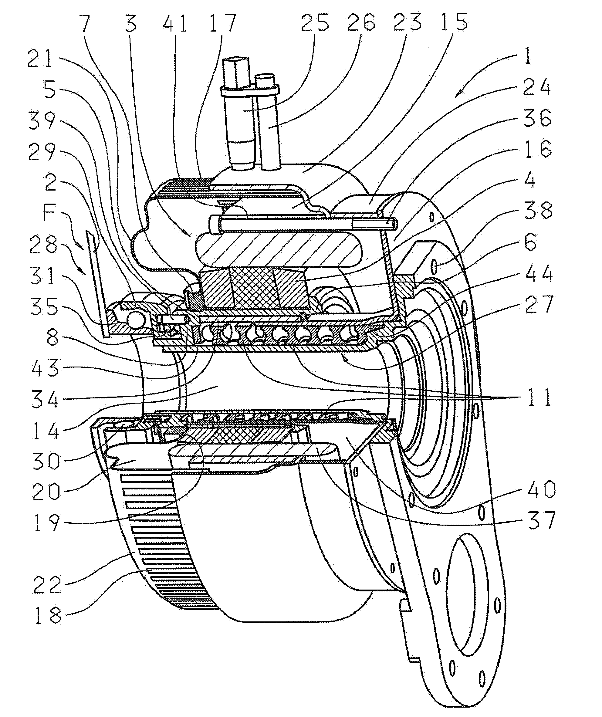
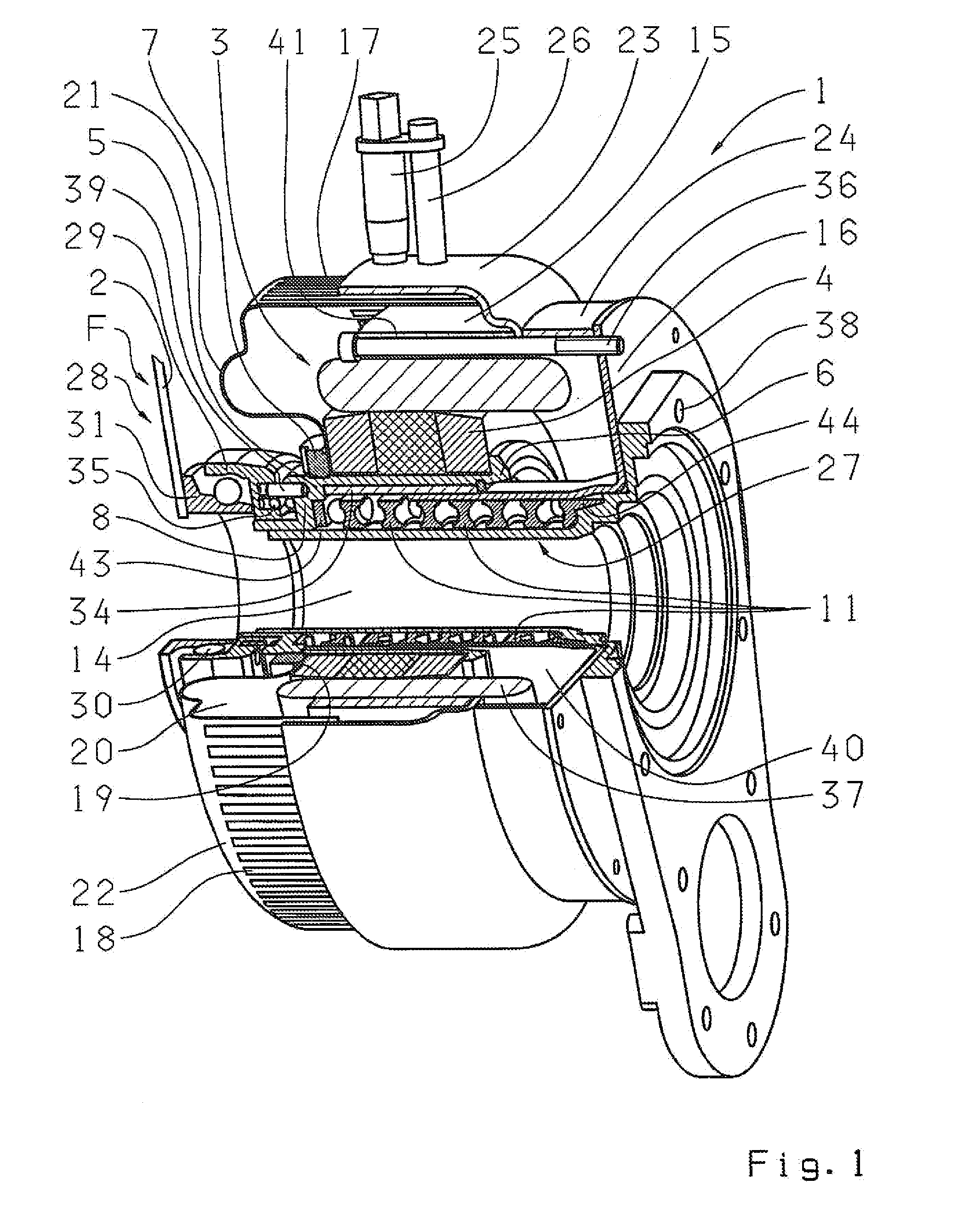
[0042]Accordingly, FIG. 1 shows an electromotive actuator 1 configured according to the invention, in a perspective and cutaway view. The part that is to be actuated in this embodiment is a vehicle component, especially a diaphragm spring 2 of a friction clutch, that is used as starting and shifting clutch in conjunction with an automatic transmission. Here, the actuator 1 is configured as a so-called central clutch release device that opens or closes the friction clutch as a function of control commands of a control device (not shown here) or else that brings it into certain slip operational positions.

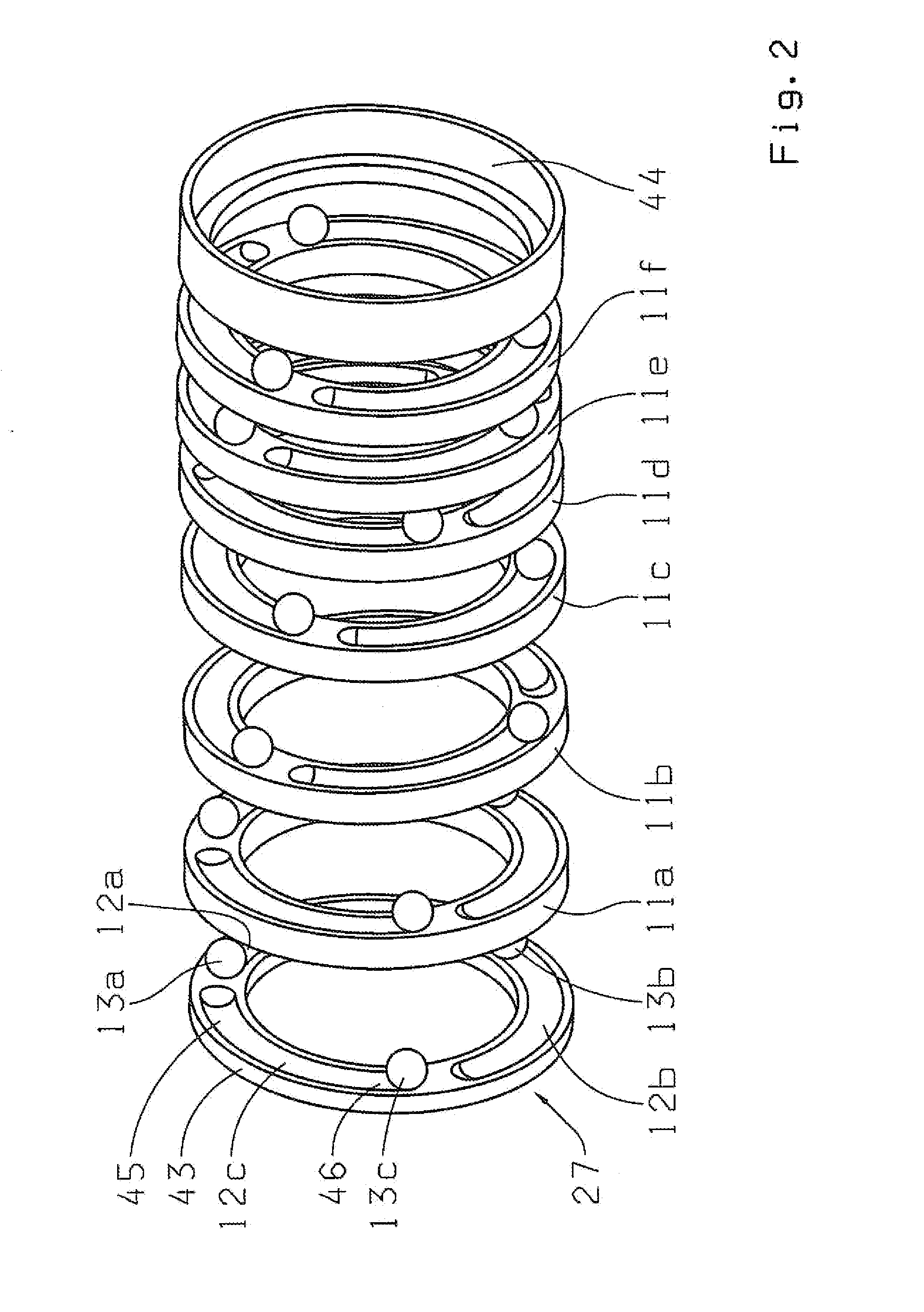
[0043]For this purpose, the actuator 1 has an electric motor 3 that can be operated in two rotational directions, as a function of the particular actuation. This electric motor 3 is connected to a deflection gear in the form of a ball-ramp adjustment device 27 that converts the rotational movement of the electric motor 3 into an axial, linear movement of the control unit of the actuat...


PUM


Abstract

An electromotive actuator for deflecting a mechanical part, comprising a rotatable component and a non-rotatable component of a deflection gear, whereby the rotatable component can be driven by an electric motor in such a way that it can be moved linearly relative to the non-rotatable component between a first position and a second position. The two components of the actuator are constituents of a ball-ramp adjustment device, whereby a rotatable component of the ball-ramp adjustment device is non-rotatably connected to the rotor of the electric motor and acts directly or indirectly on the mechanical part that is to be deflected.

Description

[0001]Priority is claimed to German Patent Application No. DE 10 2006 042 478.6, filed on Sep. 9, 2006, the entire disclosure of which is incorporated by reference herein.[0002]The present invention relates to an electromotive actuator for deflecting a mechanical part, including a rotatable component and a non-rotatable component of a deflection gear, the rotatable component driveable by an electric motor in such a way that it can be moved linearly relative to the non-rotatable component between a first position and a second position,BACKGROUND[0003]Modern vehicles contain a relatively large number of electric actuators with which the rotational movement generated by an electric motor that can be actuated by a control device is converted into a linear or rectilinear movement of the vehicle component that is to be moved. A special area of application of such actuators is in the automatic actuation of a starting and shifting clutch of a motor vehicle, whereby the component that is to ...

Claims


Application Information

Patent Timeline
IPC IPC(8): F16D3/06
CPCF16D23/12F16D23/14Y10T74/18984F16D2023/123F16D28/00
Inventor WEULE, JAN
Owner ZF FRIEDRICHSHAFEN AG
Why Eureka
Try Eureka