Illumination device for a motor vehicle

a technology for motor vehicles and nozzles, which is applied in vehicle lighting systems, measurement apparatus components, lighting and heating apparatus, etc., can solve the problems of low efficiency of devices, light beams being deflected in an undesirable direction, and absorbed within the devices,

Inactive Publication Date: 2011-05-05
AUTOMOTIVE LIGHTING REUTLINGEN GMBH
View PDF7 Cites 8 Cited by
  • Summary
  • Abstract
  • Description
  • Claims
  • Application Information

AI Technical Summary

Benefits of technology

[0010]Another advantage of the illumination device for a motor vehicle of the invention is that light of it can again penetrate the light guide unimpeded.
[0011]Another advantage of the illumination device for a motor vehicle of the invention is that a relatively high percentage of light of the device that is coupled-in the light guide will be emitted in accordance with a desired pre-defined light distribution.
[0012]Another advantage of the illumination device for a motor vehicle of the invention is that, in contrast to the first decoupling element, the second decoupling element couples the light directly out of the light guide without conducting the light again through the light guide by means of the reflector.
[0013]Another advantage of the illumination device for a motor vehicle of the invention is that the light guide can be formed from any transparent material—preferably, plastic material and, in particular, polymethylmethacrylate (PMMA).
[0014]Another advantage of the illumination device for a motor vehicle of the invention is that the light guide can be produced in great quantities simply by injection-molding.
[0015]Another advantage of the illumination device for a motor vehicle of the invention is that the decoupling elements are a single component.

Problems solved by technology

If a light guide of the device is relatively strongly curved and / or if first decoupling elements together with reflectors assigned to them of the device are arranged relatively tightly packed on the light guide, then danger exists that light beams will be deflected in an undesirable direction or be absorbed within the device.
Overall, the device, therefore, exhibits a relatively low efficiency in the case of the light guides being relatively strongly curved or first decoupling elements being arranged relatively tightly packed on the light guide.

Method used


Image

  • Illumination device for a motor vehicle
  • Illumination device for a motor vehicle
  • Illumination device for a motor vehicle

Examples


Embodiment Construction

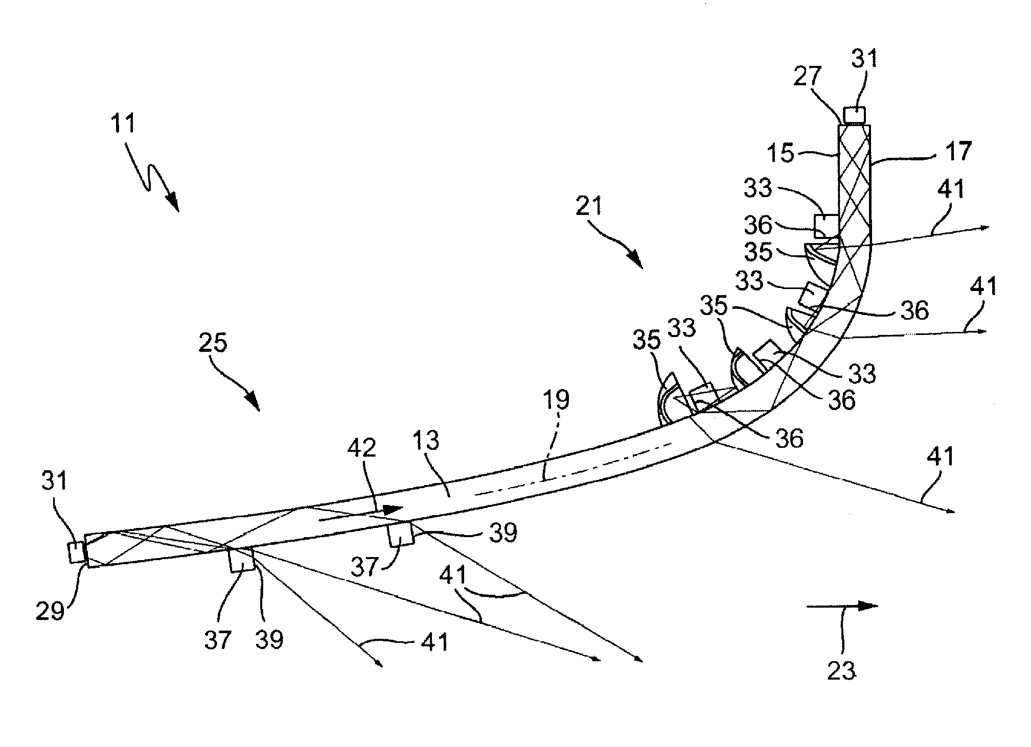
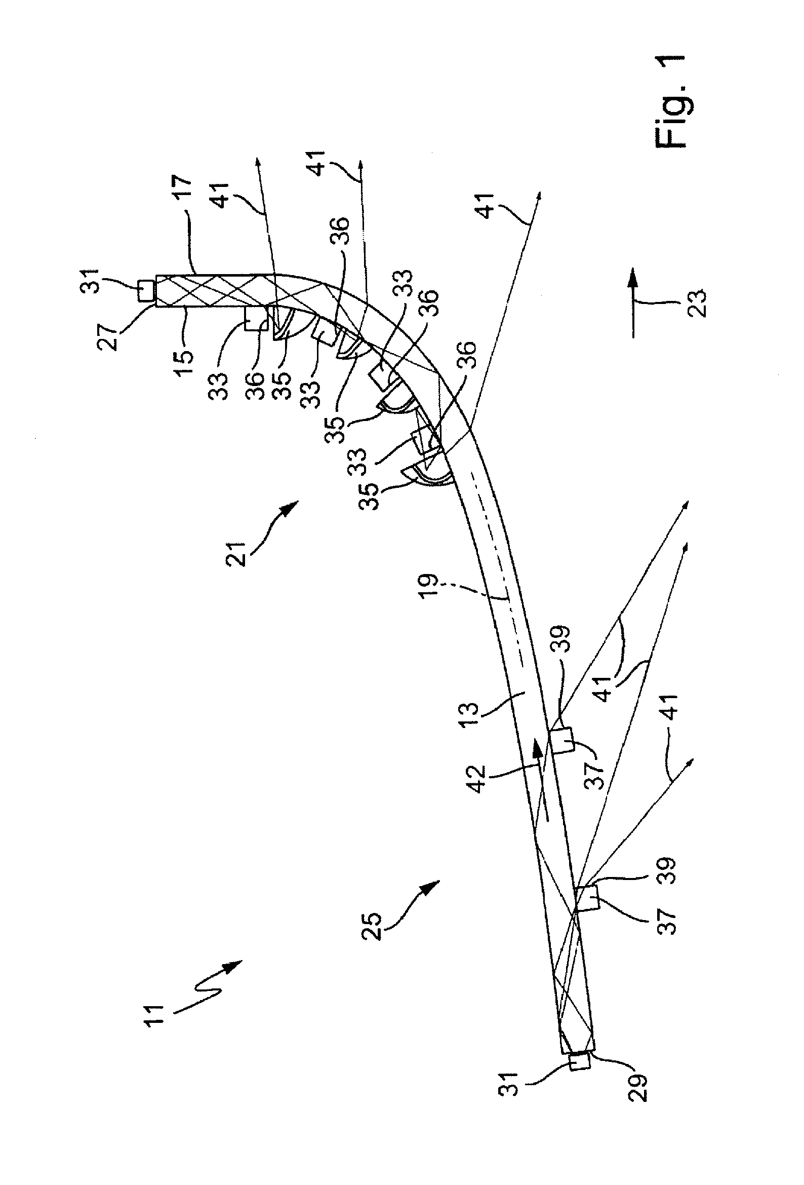
[0027]FIG. 1 shows a motor-vehicle illumination device 11. In the case of the illumination device 11, it can, for example, be a motor-vehicle headlight or a motor-vehicle light, in particular, a taillight. The illumination device 11 exhibits a curved, on the whole, plate-shaped light guide 13. The light guide 13 exhibits a substantially constant thickness so that a first side 15 of the light guide 13 runs parallel to a second side 17 of the light guide 13. The two sides 15, 17, in turn, run parallel to a longitudinal axis 19 (shown in sections in FIG. 1 for clarity's sake) of the light guide 13. In deviation from the shown embodiment, the light guide 13 can also exhibit a varying thickness along its longitudinal axis 19 so that the two sides 15, 17 are not parallel to one another.

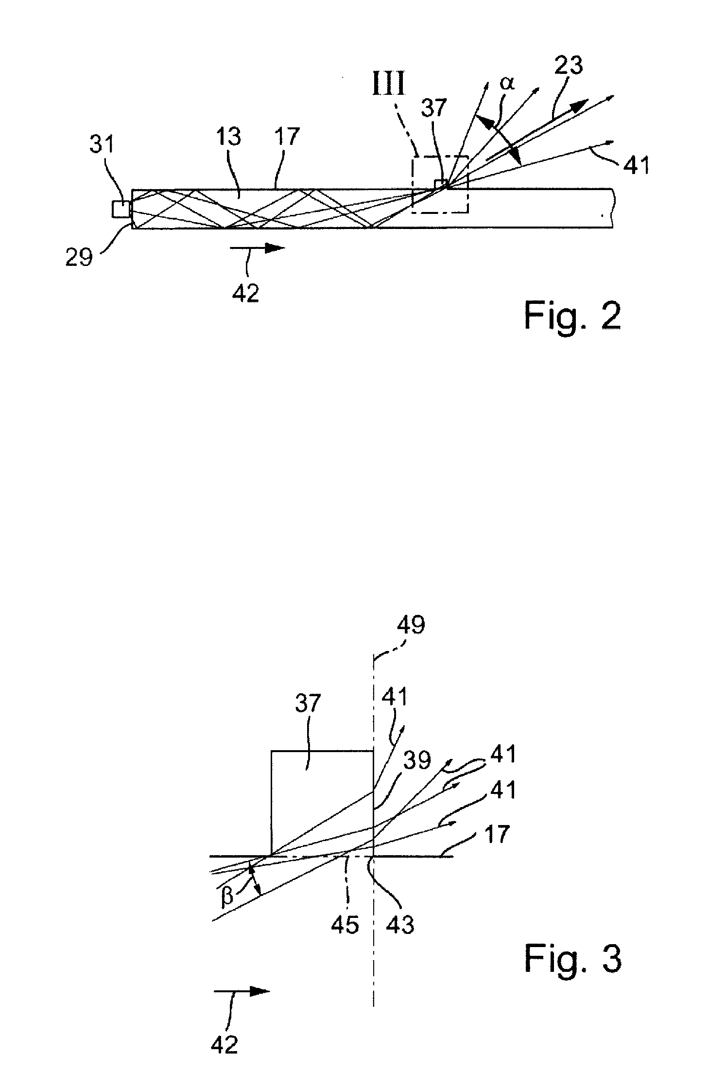
[0028]At a first section 21 of the light guide 13, the two sides 15, 17 and longitudinal axis 19 of the light guide 13 are relatively strongly inclined vis-à-vis a main direction of light emission (arrow 23...


PUM


Abstract

An illumination device (11) for a motor vehicle includes a transparent light guide (13). At least a first decoupling element (33) is formed into the light guide (13). At least one reflector (35) is assigned to the first decoupling element (33) for reflection of light coupled-out by the first decoupling element (33) and aligned and formed in such a way that at least a portion of the light reflected by the reflector (35) irradiates the light guide (13). At least one second decoupling element (37) is formed in the light guide (13) for coupling-out of light from the light guide (13) and aligned and formed in such a way that light coupled-out by the second decoupling element (37) ultimately exits the light guide (13).

Description

CROSS-REFERENCE TO RELATED APPLICATION[0001]This application claims priority to and benefit of the filing date of German Patent Application 10 2009 052 339.1 entitled “Illumination Device for a Motor Vehicle” and filed on Nov. 3, 2009.BACKGROUND OF INVENTION[0002]1. Field of Invention[0003]The invention relates, generally, to an illumination device for a motor vehicle and, more specifically, to such a device a light guide of which is relatively strongly curved and / or first decoupling elements together with reflectors assigned to them of the device are arranged relatively tightly packed on the light guide.[0004]2. Description of Related Art[0005]An illumination device for a motor vehicle is described in DE 10 2008 016 764. If a light guide of the device is relatively strongly curved and / or if first decoupling elements together with reflectors assigned to them of the device are arranged relatively tightly packed on the light guide, then danger exists that light beams will be deflected...

Claims


Application Information

Patent Timeline
Patent Type & Authority Applications(United States)
IPC IPC(8): B60Q1/00F21V13/02F21W107/10
CPCF21S48/1241F21S48/215G02B6/0055F21Y2101/02G02B6/0036F21S48/2225F21S41/24F21S43/14F21S43/235F21Y2115/10
Inventor ZWICK, HUBERT
Owner AUTOMOTIVE LIGHTING REUTLINGEN GMBH
Why Eureka
Try Eureka