Spinning device

Inactive Publication Date: 2005-02-15
SAURER GERMANY GMBH & CO KG
View PDF14 Cites 2 Cited by
  • Summary
  • Abstract
  • Description
  • Claims
  • Application Information

AI Technical Summary

Benefits of technology

Thus, an advantage of the present invention is that it is assured that the spinning device is not inadvertently opened by internal forces, even in case of possible malfunctions.
In a preferred embodiment of the present invention, a device is provided in the area of a cross arm of the spinning box housing which makes it possible to preset the maximum pivot angle of the expander roller. In case of a malfunction, such a travel limiting device prevents the expander roller from being flipped upward past a predetermined amount and, in the course of this movement, from also lifting the brake and locking lever positively fixing the spinning device in place, out of its locked position.
Furthermore, such a travel limiting device assures that a flipped-up expander roller cannot damage either the spinning device itself or adjacent components of the spinning device.
A travel limiting device can be simply produced as follows. An elongated hole recess arranged in a cross arm of the spinning box housing is placed and dimensioned in such a way that the freedom of movement of the lifting hoop for actuating the expander roller and guided in the elongated hole recess is minimized. Since the lifting hoop is connected to the pivotably seated

Problems solved by technology

Moreover, the expander roller holder is connected via a pressure lever system with an actuating lever that when acted upon during the run-up of the spinning rotor results in an increase of the pressure force of the tangential belt against the respective rotor shaft.
However, under rare exceptional conditions, for example in the case of a defect in the tangent

Method used


Image

  • Spinning device
  • Spinning device
  • Spinning device

Examples


Example

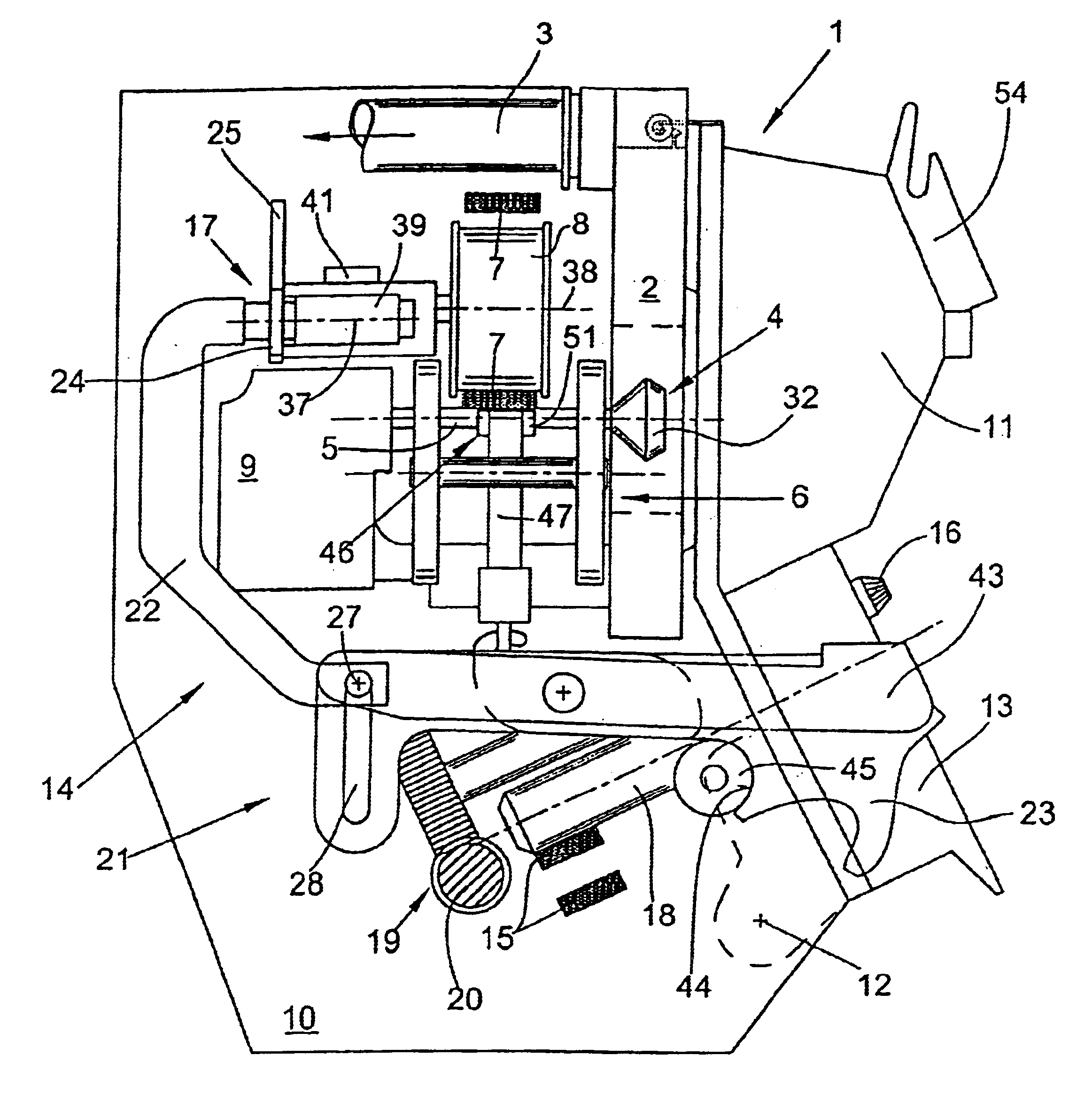
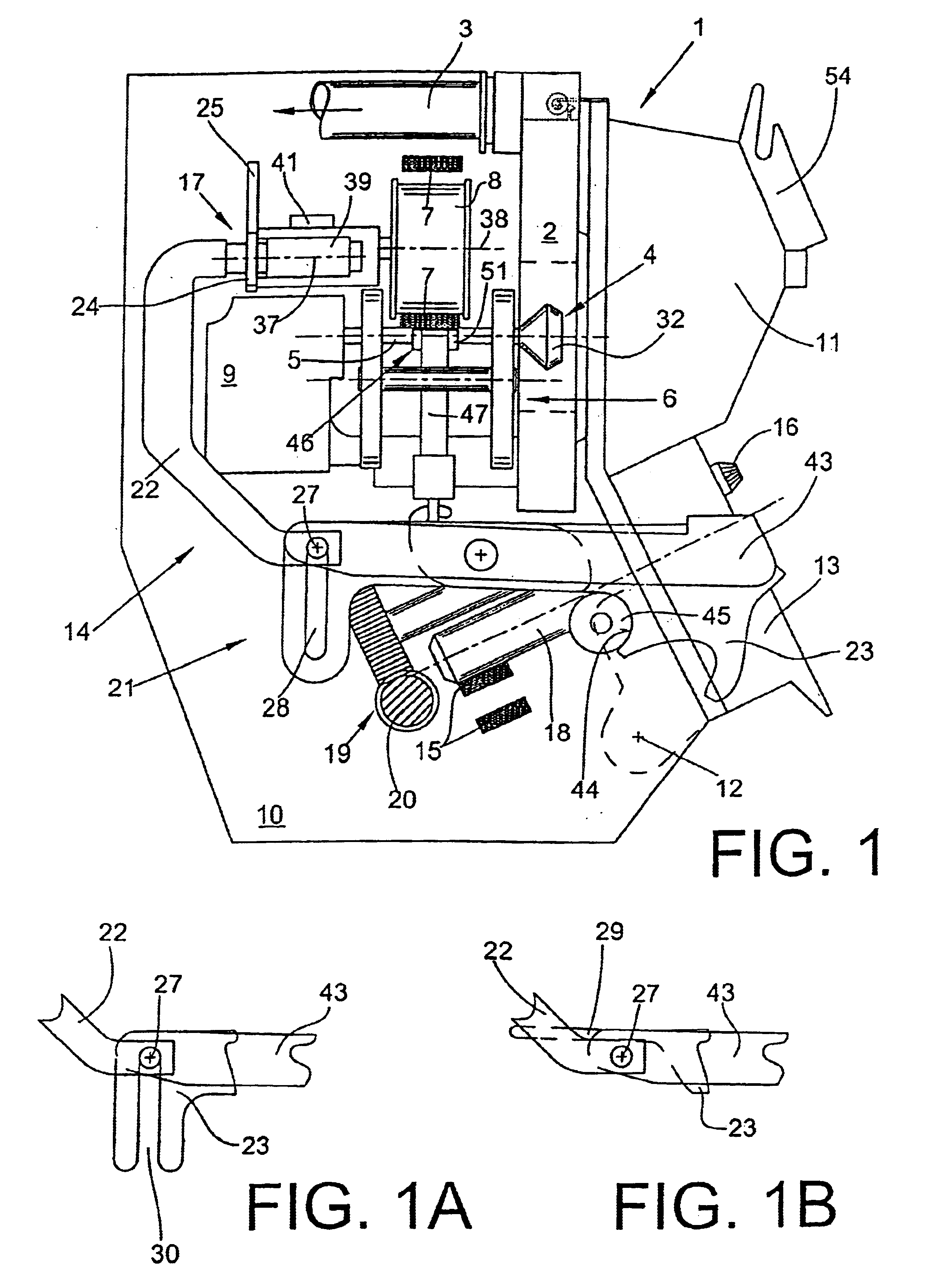
An open-end spinning device 1 is shown schematically and in a lateral view in FIG. 1. In FIG. 1, the open-end spinning device 1 is shown in a state ready for operation, meaning that the rotor housing 2, in which the spinning cup 32 of a spinning rotor 4 turns at a high number of revolutions, is closed by a cover element 11.

In this embodiment, the rotor housing 2 is connected in a known manner by means of a pneumatic line 3 to a vacuum source (not shown). The vacuum is needed for spinning.

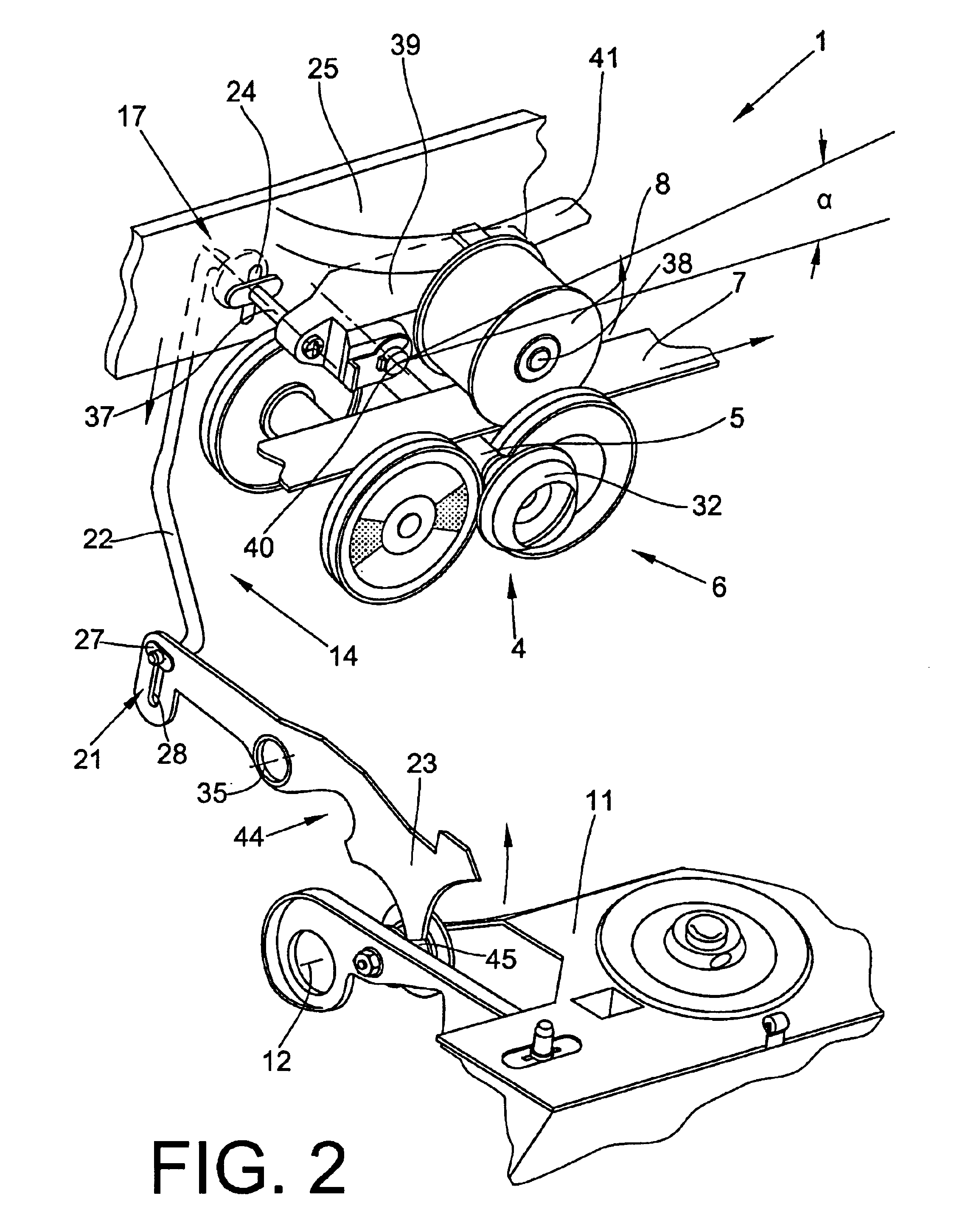
In a customary manner, the rotor shaft 5 of the spinning rotor 4 is seated in the wedge gaps of a support disk bearing 6 and is driven by a tangential belt 7 that extends over the length of the machine and in turn is acted upon by an expander roller 8 in the area of the rotor shaft 5.

The spinning rotor 4 is further supported in the axial direction by an appropriate axial bearing 9, such as a permanent magnet bearing.

In this embodiment, the rotor housing, as well as the bearing devices 6 and 9 are fi...


PUM

PropertyMeasurementUnit
Pressureaaaaaaaaaa
Angleaaaaaaaaaa
Lengthaaaaaaaaaa

Abstract

A spinning device comprising a spinning box housing; a spinning rotor having a spinning cup on a rotor shaft; a cover element; a traveling belt acting tangentially on the rotor shaft; a rotor brake; a pivotable expander roller moveable within a maximum pivot angle via a pressure lever system connected to the brake gear of the rotor brake between an operative position when the spinning box is closed in an inoperative position wherein the expander roller is automatically lifted off the tangential belt and the rotor brake is applied to the rotor shaft when the spinning box is opened; a brake and locking lever having a locking recess in contact with an arresting roller arranged on the cover element; and an arrangement in the pressure lever system for absorbing shock-like forces acting on the expander roller and for preventing the forces from being transmitted to the brake and locking lever.

Description

CROSS-REFERENCES TO RELATED APPLICATIONSThis application claims the benefit of German patent application 10211817.5 filed Mar. 16, 2002, herein incorporated by reference.FIELD OF THE INVENTIONThe present invention relates generally to spinning devices, and more particularly to spinning devices for open-end rotor spinning machines.BACKGROUND OF THE INVENTIONSpinning devices for open-end rotor spinning machines are known.For example, German Patent Publication DE 197 08 944 A1 discloses an open-end spinning machine with a spinning rotor, having a rotor shaft supported on a support disk bearing and a rotor cup that rotates in a rotor housing, that can be closed by means of a cover element and can be charged with a vacuum.German Patent Publication DE 39 42 402 C2 discloses a similar spinning device. With this known spinning device, the rotor shaft of the rotor is also rotatably seated in two wedge gaps of a support disk bearing, and a tangential belt extending over the length of the mach...

Claims


Application Information

Patent Timeline
IPC IPC(8): D01H4/00D01H4/12
CPCD01H4/12
Inventor WASSENHOVEN, HEINZ-GEORGSPITZER, MICHAELHAAKEN, DIETERGATZKE, HARRYSCHELTER, DETLEFKLACZYNSKI, ELISABETHSCHRODER, HANS-JOSEF
Owner SAURER GERMANY GMBH & CO KG
Why Eureka
Try Eureka