Knotless suture anchor and receptacle combination

a knotless and anchoring technology, applied in the field of knotless suture anchors, can solve the problems of insufficient strength of bone structure to hold knotless suture anchor types, ineffective knotless suture anchors that can support the tendon to the bone, and inability to achieve the effect of retaining the anchor, ensuring the stability of the anchor, and enhancing the holding surface area

Active Publication Date: 2009-11-26
DEPUY SYNTHES PROD INC
View PDF26 Cites 27 Cited by
  • Summary
  • Abstract
  • Description
  • Claims
  • Application Information

AI Technical Summary

Benefits of technology

[0016]A feature of one embodiment of this invention is to provide a receptacle with a cylindrical shaped main body having a helix thread around the outer periphery and a central bore having a reduced diameter portion at the distal end and capable of accepting a removable knotless suture anchor with a locking portion having a larger diameter than the diameter of the reduced portion so as to permit the winged portion of the anchor to pass there-through and when deployed being capable of impaling the bone of the patient where the knotless suture anchor is locked in place in the receptacle when deployed.
[0017]A feature of this invention is to provide a receptacle that utilizes a main body with a large diameter portion and a small diameter portion that carries a helical thread

Problems solved by technology

As is well known in the medical field, there is an increasingly occurring problem where connective tissue, such as tendons and ligaments, tear or detach from the associated bone.
Unfortunately, the known knotless types of suture anchors that are capable of supporting the tendon to the bone is not efficacious for certain types of patients or where the surgeon inadvertently or aggressively removes the outer cortical layer of the bone while preparing the area of concern during the operative procedure or an anchor has been removed from the bone cavity and another anchor is intended to replace it.
In these instances the bone structure is not sufficiently strong to hold the knotless suture types of anchors and under the circumstances the anchor or suture anchor will avulse from the bone.
None of

Method used


Image

  • Knotless suture anchor and receptacle combination
  • Knotless suture anchor and receptacle combination
  • Knotless suture anchor and receptacle combination

Examples


Embodiment Construction

[0036]While this invention is being described in its preferred embodiment as having a specific type of rivet or anchor utilized in the chamber of a receptacle, as would be appreciated by one skilled in this art, other types of anchors or variations thereof can be utilized without departing from this invention. However, in accordance with this invention, the specific anchor inserted in the receptacle is of the type that can be utilized with or without a receptacle.

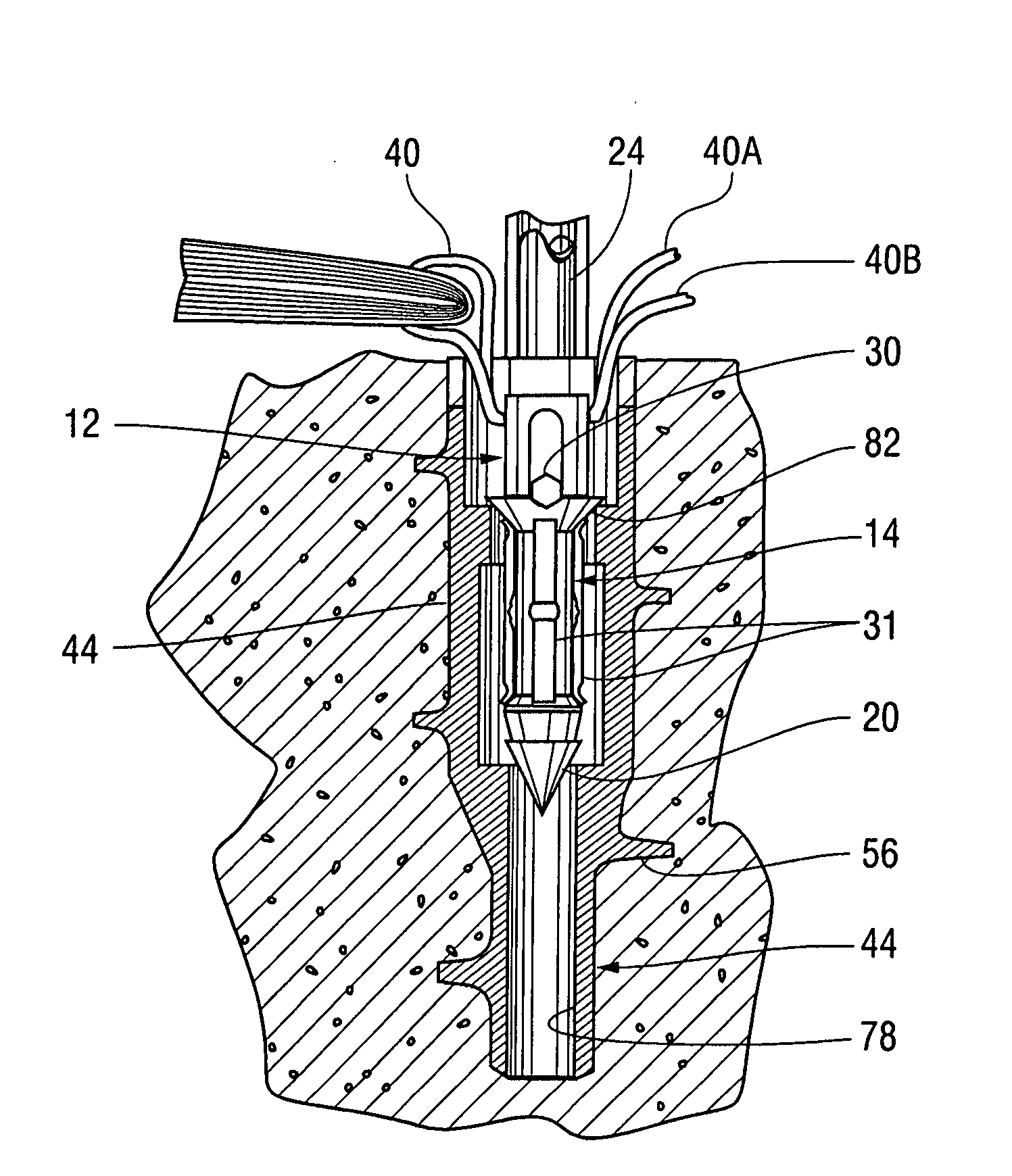
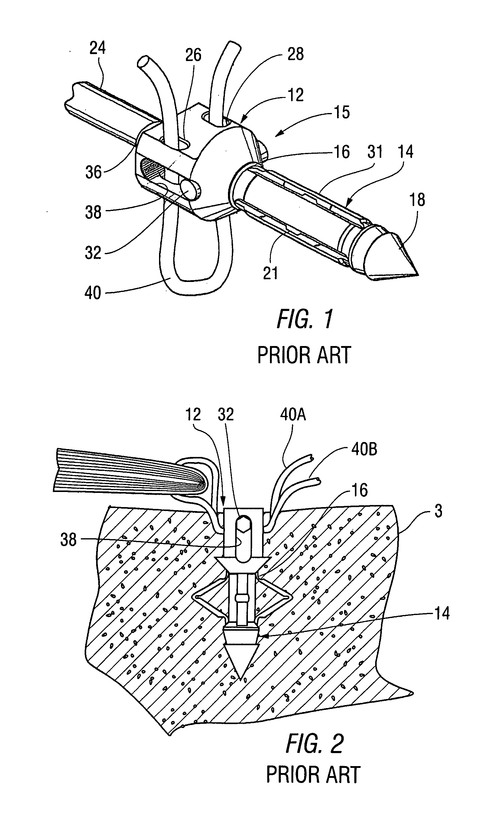
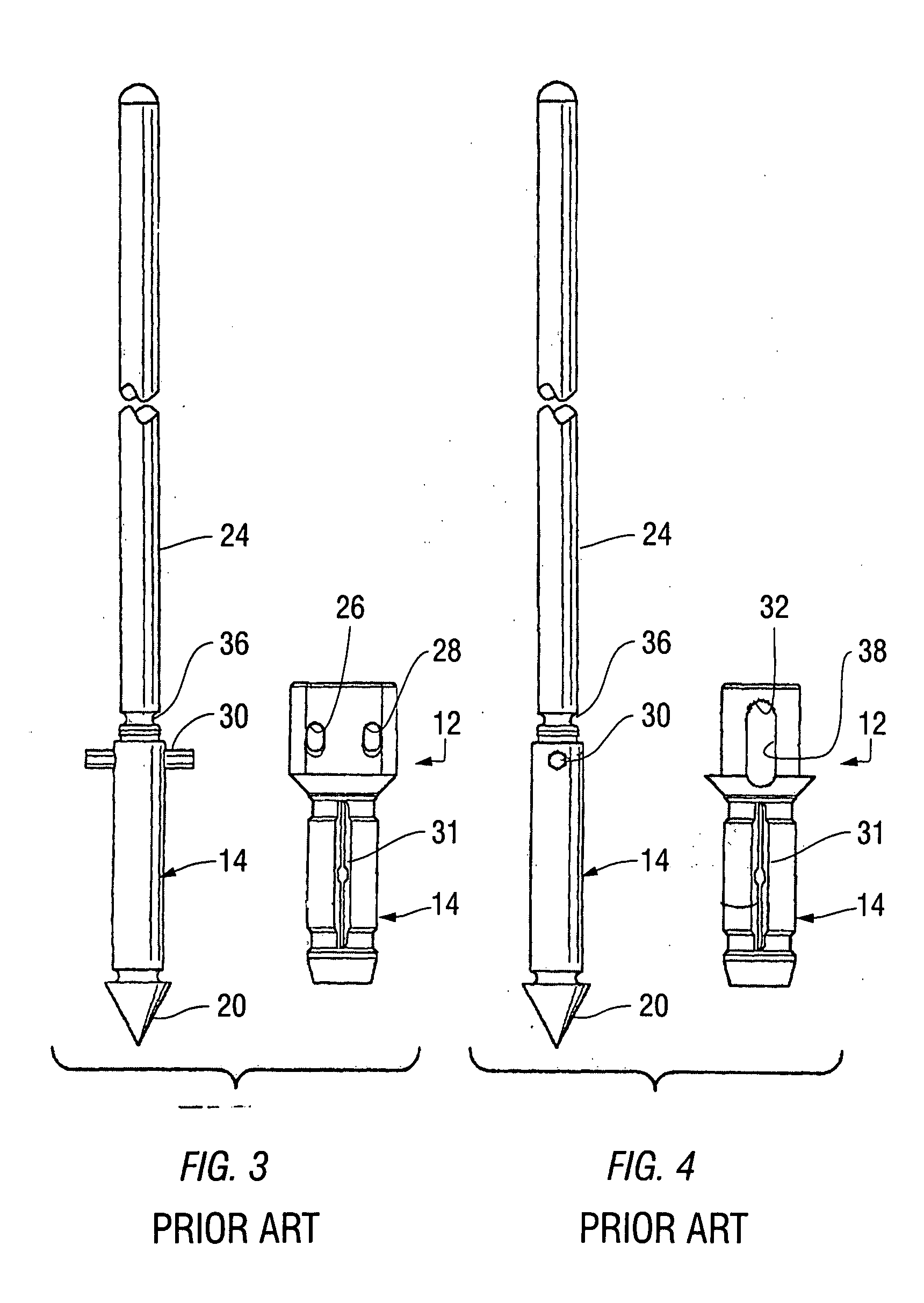
[0037]Referring next to the prior art anchor of the type that is commercially available and described in U.S. Pat. No. 7,144,415, supra, as shown in FIGS. 1 through 4, the knotless suture anchor generally illustrated as reference numeral 10 includes a the suture locking mechanism generally illustrated by reference numeral 12 and the anchor generally illustrated as reference numeral 14. The anchor 14 includes a cylindrical proximate end 16 and a cylindrical distal end 18, axially spaced there from. A pointed end portion 20 p...


PUM


Abstract

A threaded receptacle for receiving a commercially available knotless suture anchor is designed to secure sutures for tying soft tissue in patience that have bone characteristics where the typical anchor is avulsed because of the weakness of the bone structure, a cavity exists in the bone where an anchor has been rev. The threaded receptacle includes a helical thread that is maximized to provide sustaining surface and includes a central bore and an internal flange that is dimensioned to provide a central opening to allow the knotless suture anchor to pass into a cavity and prevent the knotless suture anchor from being expulsed when deployed. The internal dimension of the cavity is designed to cause the tips of the wings of the anchor to fold to assure sufficient holding structure. In a second embodiment the reduced diameter portion is at the end of the receptacle so that the anchor passes through the end of the receptacle and the locking portion remains within the receptacle having both the receptacle and anchor serving as a means for securing the mechanism to the bone.

Description

RELATED APPLICATIONS[0001]This invention relates to the anchor disclosed and claimed in U.S. Pat. No. 7,144,415 granted to the joint inventors of this patent application on Dec. 5, 2006 entitled ANCHOR / SUTURE USED FOR MEDICAL PROCEDURES and assigned to the same assignee as this patent application and is incorporated in its entirety by reference in this patent application.FEDERALLY SPONSORED RESEARCH OR DEVELOPMENT[0002]Not applicableTECHNICAL FIELD[0003]This invention relates to a knotless suture anchor and more particularly to the combination of this type of anchor and a receptacle for attaching soft tissue to the bone of a patient used in medical procedures.BACKGROUND OF THE INVENTION[0004]As is well known in the medical field, there is an increasingly occurring problem where connective tissue, such as tendons and ligaments, tear or detach from the associated bone. While this invention is not limited to the method of incisions used in this type of operation, there is a trend to us...

Claims


Application Information

Patent Timeline
IPC IPC(8): A61B17/04
CPCA61B17/0401A61B17/0487A61B2017/0409A61B2017/0414A61B2019/307A61B2017/044A61B2017/0445A61B2017/0448A61B2017/0437A61B2090/037A61B17/864
Inventor ANSPACH, III, WILLIAM E.DEL RIO, EDDY H.
Owner DEPUY SYNTHES PROD INC
Why Eureka
Try Eureka