Method and Device for Producing Content Filling Bottle

a filling bottle and content technology, applied in the direction of filling without pressure, packaging goods, caps, etc., can solve the problem of tools not being installed, and achieve the effect of reliably preventing inadvertent deformation of the bottom part, accurate positioning, and reliably supporting

Active Publication Date: 2009-12-03
CO2 PAC
View PDF19 Cites 73 Cited by
  • Summary
  • Abstract
  • Description
  • Claims
  • Application Information

AI Technical Summary

Benefits of technology

[0029]Thus, when the bottom part recessing means inverts and recesses the inversion part inwardly into the bottle, the body part gripping means and bottom part supporting means sandwichingly hold the shoulder part and the bottom part from above and from below. Consequently, when the inversion part is pressed, the bottom part can be accurately positioned. The inversion part can thus be reliably inverted and recessed inwardly into the bottle. Moreover, since the bottom part supporting means comprises a supporting concave part corresponding to the bot

Problems solved by technology

Thus, during the content filling step, the a

Method used


Image

  • Method and Device for Producing Content Filling Bottle
  • Method and Device for Producing Content Filling Bottle
  • Method and Device for Producing Content Filling Bottle

Examples


first embodiment

[0055]First, the present invention will be described.

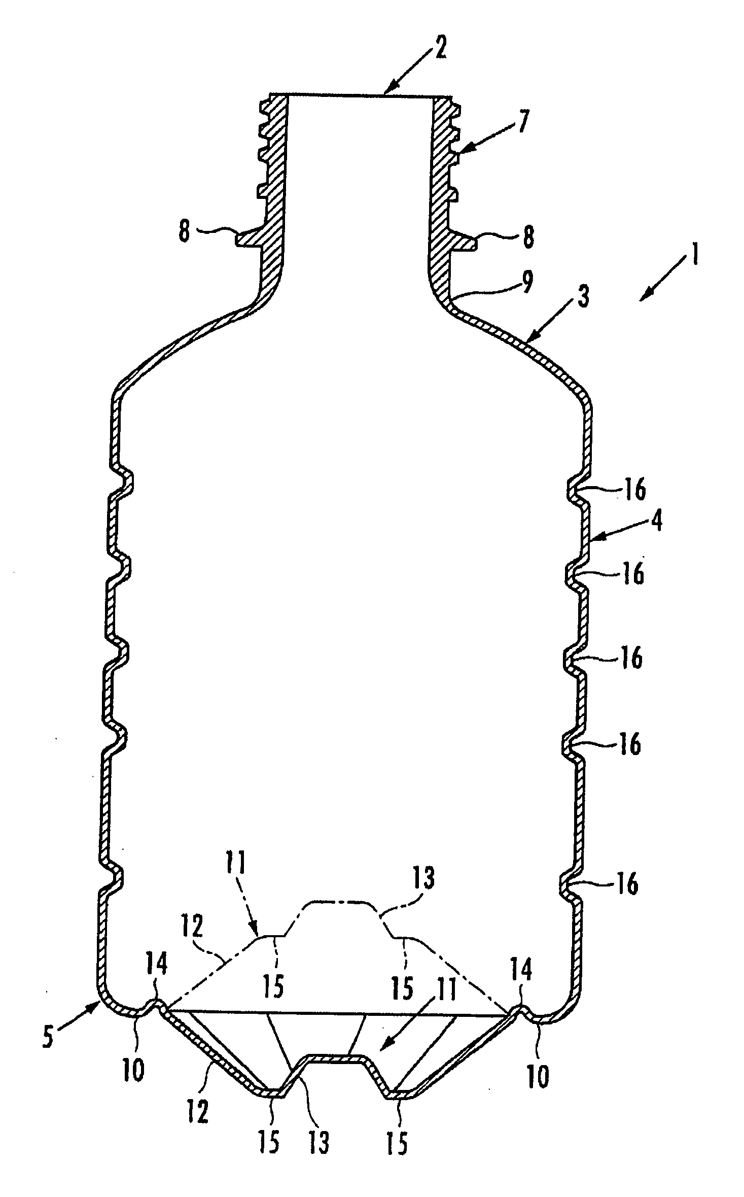
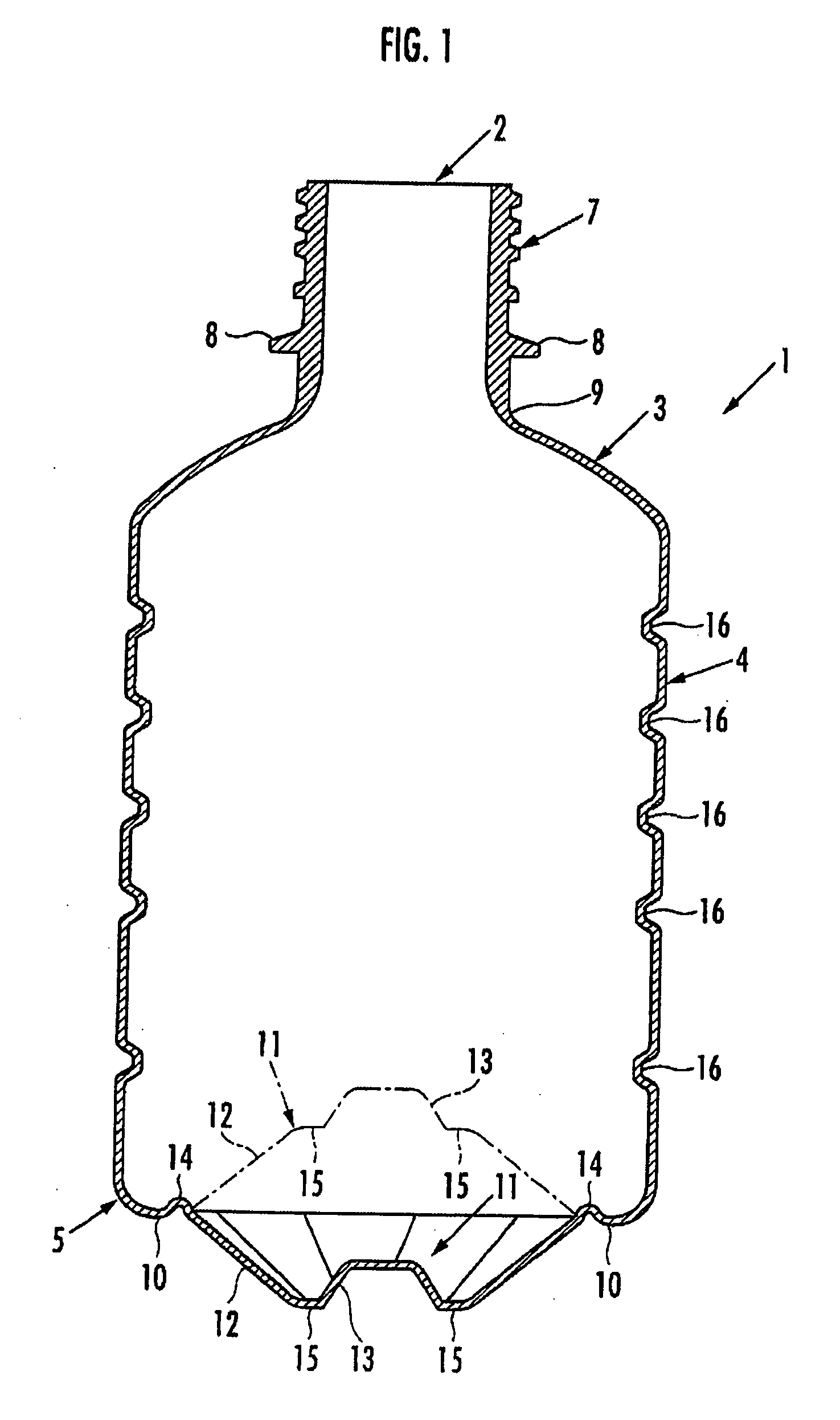
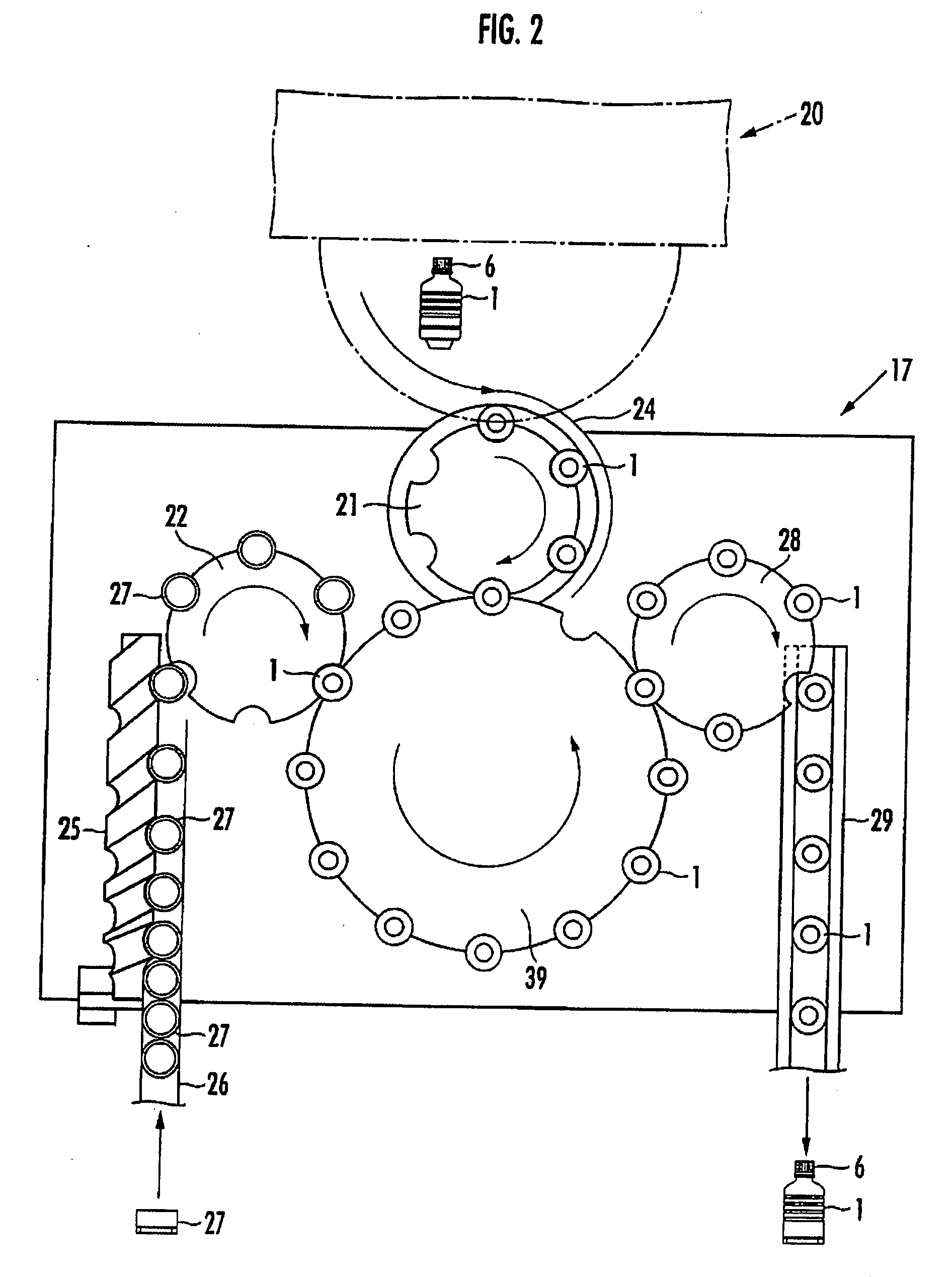
[0056]A device according to the first embodiment produces a content filling bottle with contents such as a drink filled therein. A part of the device comprises auxiliary tool installing means 17, shown in FIG. 2, and bottom part recessing means 18 and auxiliary tool separating means 19, which are shown in FIG. 3.

[0057]Although not shown in the drawings, the filler and a capper 20 (shown in FIG. 2 by an alternate long and short dash line) are provided upstream of the auxiliary tool installing means 17; the filler is content filling means for filling the contents into the bottle 1 (see FIG. 1), the content filling means being configured in a well-known manner, and the capper 20 is sealing means for sealing the bottle 1 with a cap 6, the sealing means being configured in a well-known manner.

[0058]As is well-known, the filler performs either hot filling in which heated liquid contents in a high temperature state are filled or aseptic ...

second embodiment

[0081]Now, the present invention will be described.

[0082]A device according to the second embodiment produces a content filling bottle with contents such as a drink filled therein. The device according to the second embodiment comprises bottom part recessing means 217, shown in FIG. 16, as an essential part.

[0083]Although not shown in the drawings, a filler and a capper (not shown in the drawings) are disposed upstream of the bottom part recessing means 217; the filler is content filling means of a well-known configuration for filling the contents into the bottle 1 (see FIG. 1), and the capper is sealing means of a well-known configuration for sealing the bottle 1 with the cap 6.

[0084]In the second embodiment, the aseptic filling is performed, in which the sterilized liquid contents at the ordinary temperature are filled into the bottle. As is well known, a sterilization treatment device for the bottle 1 is provided upstream of the filler to set an upstream side including the capper...


PUM

PropertyMeasurementUnit
Temperatureaaaaaaaaaa

Abstract

The present invention provides a method and device for producing a content filling bottle including a bottom part that is inverted between a concave shape and a convex shape to prevent a body part from being subjected to reduced pressure deformation, the method and device being capable of efficiently producing a sanitary and high-quality content filling bottle. Contents are filled into an empty bottle 1 with an inversion part 11 projecting outwardly from the body part. A cap 6 is fitted onto an opening of the bottle 1 to seal the bottle 1. An auxiliary tool 27 is then installed on the bottom part 5 of the bottle 1. Then, the bottom part of the bottle 1 with the auxiliary tool 27 installed thereon is supported via the auxiliary tool 27. The downwardly projecting inversion part 11 is pressed up so as to be inverted and recessed inwardly into the bottle 1. Subsequently, with the opening of the bottle 1 gripped, the auxiliary tool 27 is separated from the bottle 1.

Description

TECHNICAL FIELD[0001]The present invention relates to a method and device for producing a content filling bottle, and more specifically, to a method for producing a content filling bottle by filling liquid contents into a synthetic resin bottle having a bottom part formed to partly project outwardly in an axial direction of a body part so that the projecting part can be inverted and recessed inwardly into the body part, along with a device for carrying out the method.BACKGROUND ART[0002]As a content filling bottle, which accommodates liquid contents such as a drink therein, for example, a bottle (PET bottle) made by blow forming a polyethylene-terephthalate material has been known.[0003]With this type of bottle, when an opening of the bottle is hermetically sealed with a cap and the contents of the bottle are then cooled, a decrease in the volume of the contents or the like reduces the pressure in the bottle. This may deform a body part of the bottle, making the appearance of the bo...

Claims


Application Information

Patent Timeline
IPC IPC(8): B67C3/24B65B3/04B65D1/02
CPCB65D1/0261B65D79/005B67C2003/226B67C3/045B67C3/04
Inventor MIYAZAKI, SHUNZOSATO, YASUHIROWATANABE, AKIOKIMURA, MASARU
Owner CO2 PAC
Why Eureka
Try Eureka