
Tool and method for tire traction device installation

a tire traction device and tool technology, applied in non-skid devices, vehicle components, transportation and packaging, etc., can solve the problems of chain placement and difficult installation, and achieve the effect of increasing the safety margin of the user and safe and easy us

Inactive Publication Date: 2009-12-03
STEWART DENNIS I
View PDF12 Cites 9 Cited by
  • Summary
  • Abstract
  • Description
  • Claims
  • Application Information

AI Technical Summary

Benefits of technology

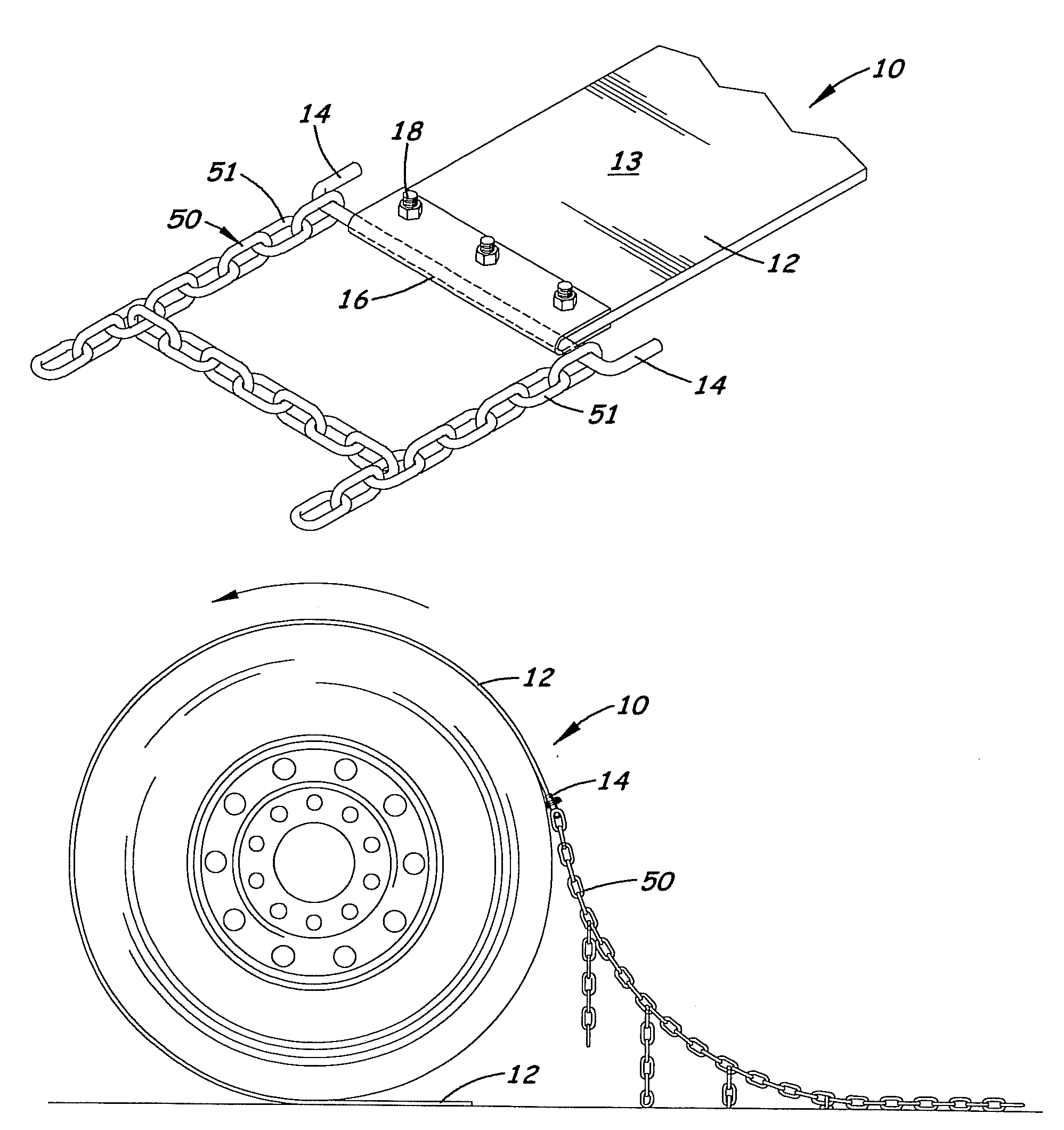
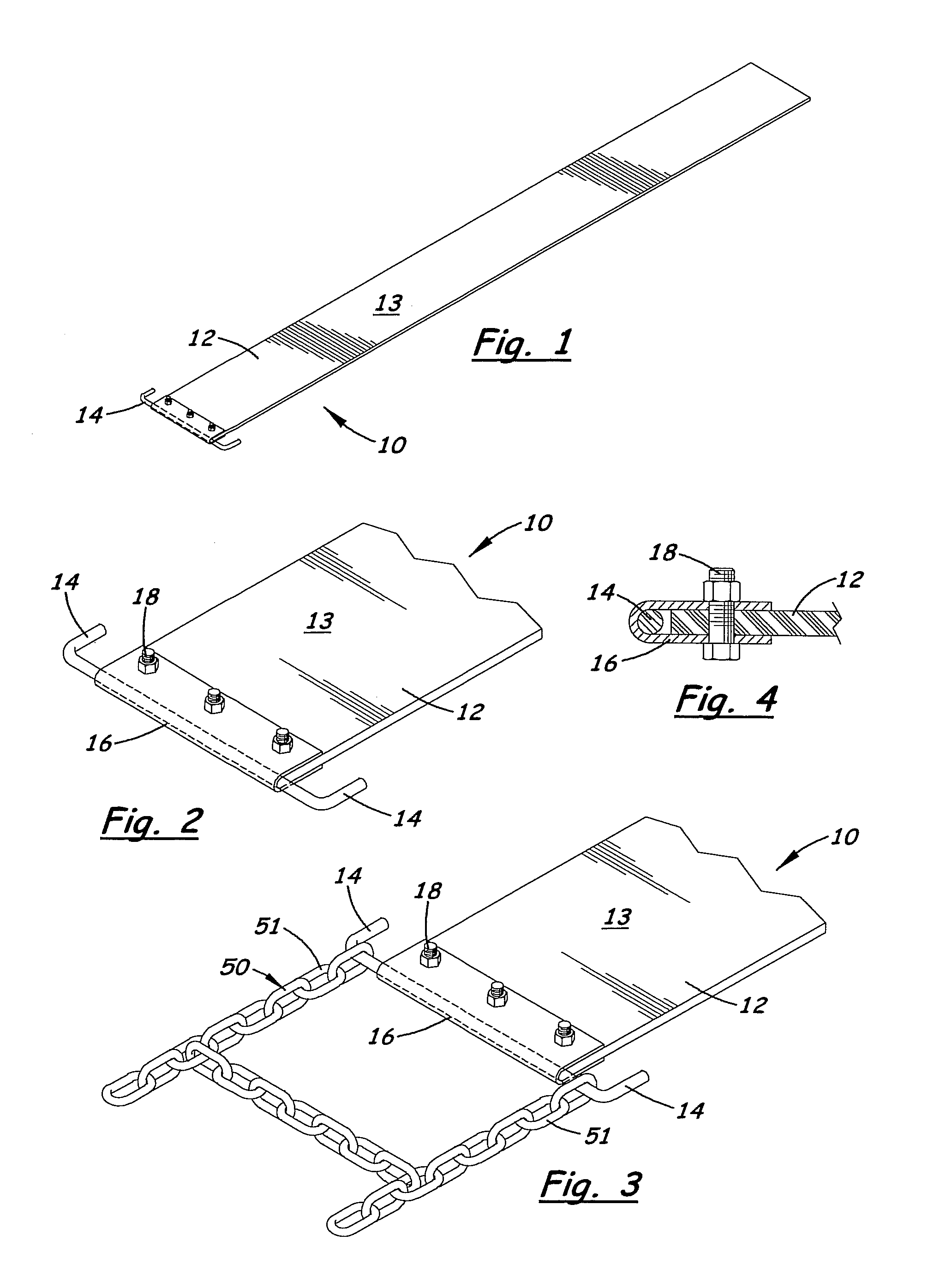
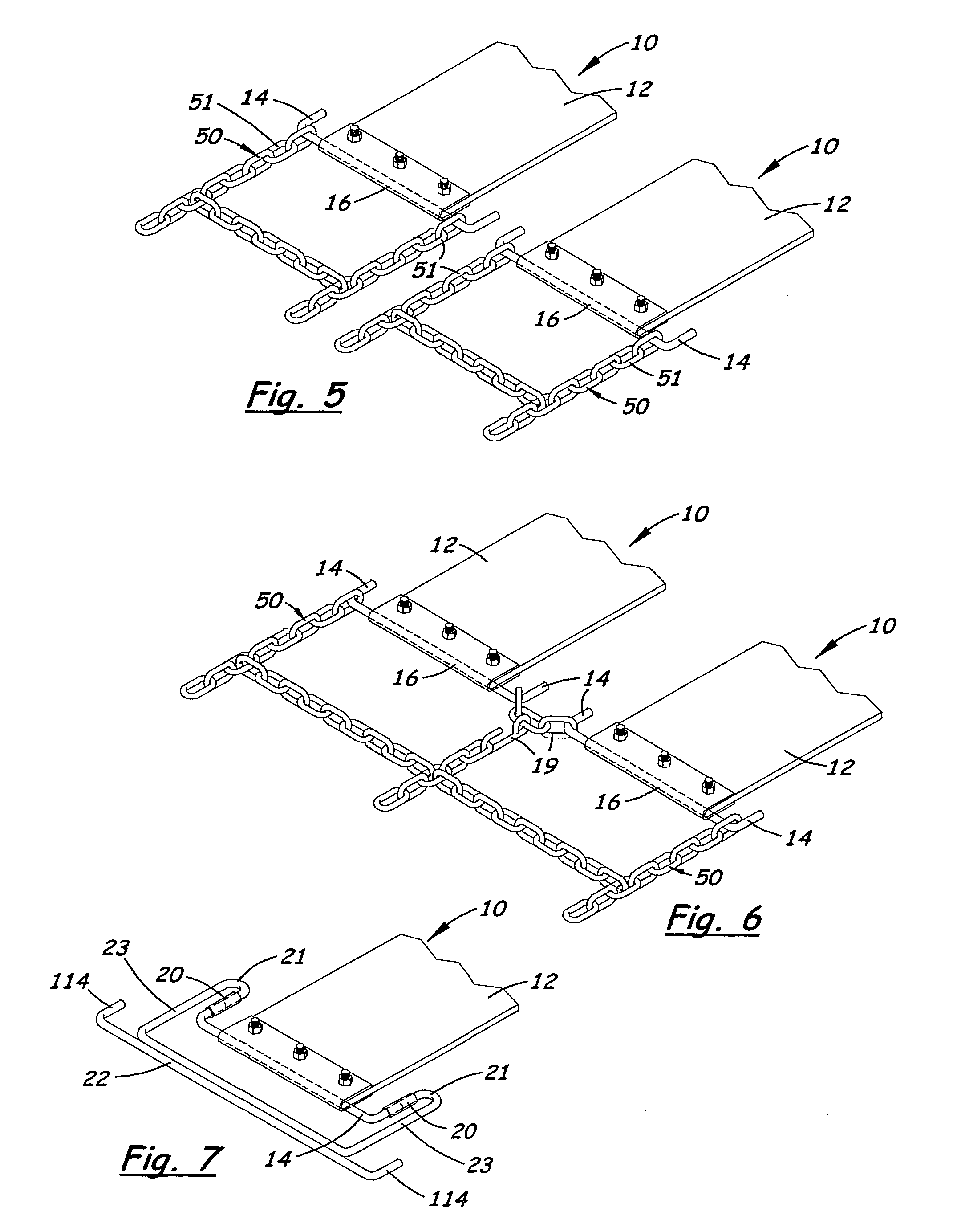
"The present invention is a device and methods for safely and easily installing tire traction devices, such as chains, on vehicle tires. The device is an extension that is attached to the traction device and used as a leader to guide and pull the traction device around the tire. The extension is attached to the traction device and is designed to keep it in place on the tire as the driver moves the vehicle. The extension is easy to install and remove, and it is designed to lie on the ground behind or in front of the tire. The extension is made of a flat and continuous belt that has a high coefficient of friction with the tire tread to prevent sliding and twisting during movement. The extension is connected to the traction device with a connector that keeps the two parallel and their central longitudinal axes co-linear. The invention includes a single extension for a single tire, multiple extensions for multiple traction devices, or a single extension that connects to an extra-wide traction device. The invention increases the margin of safety for the user compared to conventional means of installing tire chains."

Problems solved by technology

The difficulties are made worse by the need to place the chain around the tire, typically in cramped quarters and frequently in foul, cold weather.

Method used


Image

  • Tool and method for tire traction device installation
  • Tool and method for tire traction device installation
  • Tool and method for tire traction device installation

Examples


Embodiment Construction

[0033]Referring to the Figures, there are shown several, but not the only, embodiments of the invented tire chain installation device used to aid in the installation of tire chains upon vehicle tires.

[0034]A typical traction chain comprises two spaced runner chains that run the length of the traction chain, and transverse or “cross” chains that connect the runners. The runners extend circumferentially around the tire at the sides of the tire and the cross-chains extend transversely across the tire tread to provide traction. Alternative traction chains for dual tires include three spaced runners and cross-chains extending transversely between the three runners. The invented tool may be used or adapted to be used with these and other traction devices, including traction devices that are made of other materials than chain link. For example, there may be traction devices that use cable rather than chain links, and / or that use spike or stud type protrusions to provide traction. The term ...


PUM


Abstract

A tire chain installation tool comprises an elongated member that is connectable to a traction chain or other traction device and that acts as an extension and guide for leading or pulling the traction chain onto a tire. The tool receives one end of the tire traction chain, and an elongated belt of the tool is placed around the tread surface of a vehicle tire. Upon rotation of the tire due to movement of the vehicle, friction between the tire and belt (and capture of the belt between the tire and the ground / road) cause the belt and hence the tire traction chain, to be drawn around the circumference of the vehicle tire. Thus, the traction chain is placed in good position to be fastened without the struggle and discomfort frequently associated with installing chains on a vehicle. The preferred belt is easier to lift and manipulate than the traction chain and does not need to be positioned or manipulated in the space behind the tire (away from the user) or in the space between dual tires.

Description

[0001]This application is a continuation-in-part of and claims priority of prior pending U.S. application Ser. No. 11 / 708,787, entitled “Tool and Method for Tire Traction Device Installation, filed on Feb. 20, 2007, and issuing on Jun. 9, 2009, as U.S. Pat. No. 7,543,618.BACKGROUND OF THE INVENTION[0002]1. Field of the Invention[0003]The present invention relates generally to systems used to aid in the installation of traction devices upon vehicle tires. More specifically, the preferred embodiment is a self-contained tool that may be employed in the installation of traction chains upon a vehicle tire of any size and shape and that utilizes the rotation of the vehicle tire provided by vehicle power to draw the traction chain about the circumference of the vehicle tire. The use of the tool and method will be recognized as extremely practical by those persons required to install tire chains upon vehicle tires, especially large truck tires, where the traction chains are quite heavy and ...

Claims


Application Information

Patent Timeline
Patent Type & Authority Applications(United States)
IPC IPC(8): B60C27/06
CPCB60C27/14
Inventor STEWART, DENNIS I.
Owner STEWART DENNIS I
Learn More