Optimized machining process for cutting tubulars downhole

a technology of machining process and tubular device, which is applied in the direction of fluid removal, earth drilling and mining, borehole/well accessories, etc., can solve the problems of requiring replacement and unusable tubular device parts

Active Publication Date: 2009-12-03
BAKER HUGHES INC
View PDF41 Cites 29 Cited by
  • Summary
  • Abstract
  • Description
  • Claims
  • Application Information

AI Technical Summary

Benefits of technology

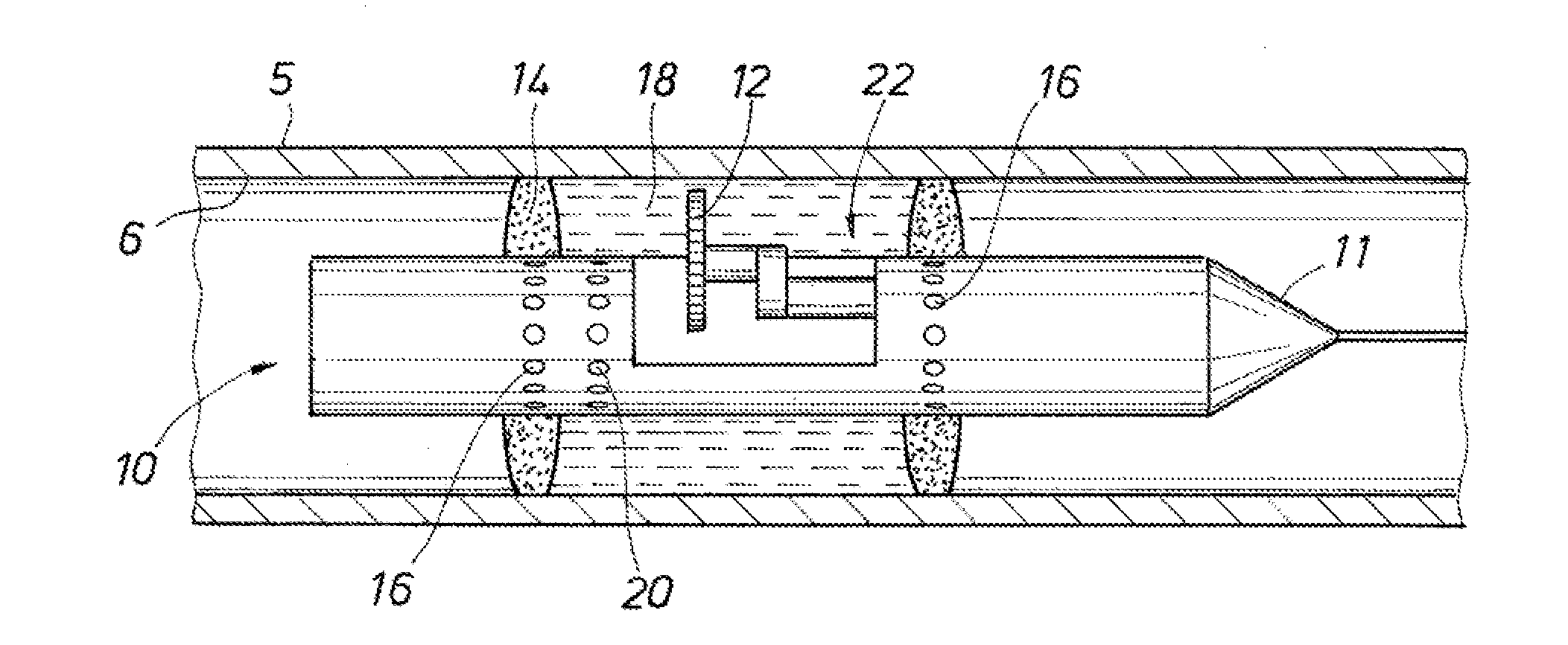
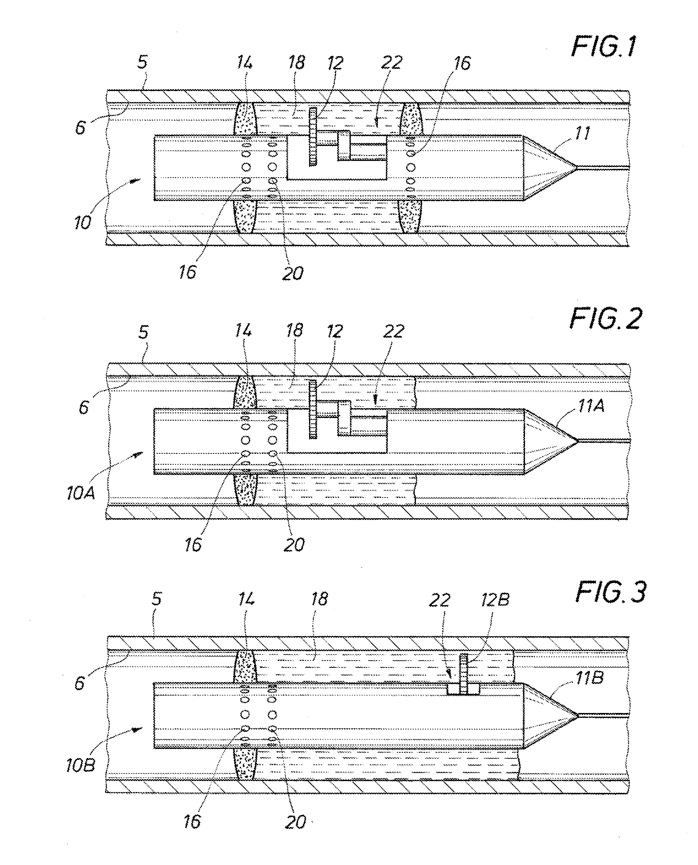
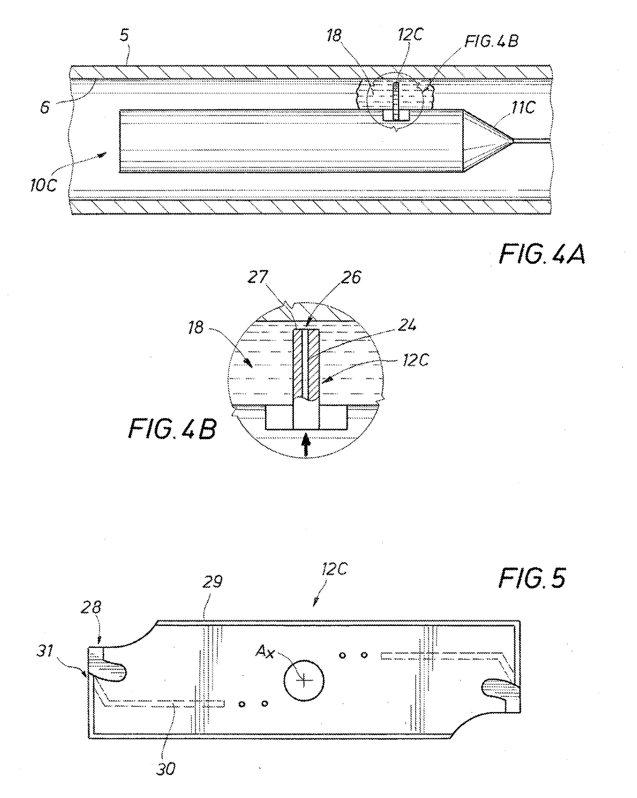
[0006]Disclosed herein is a cutting tool and method wherein lubrication is delivered during cutting. The system employs a rotating blade and a lubrication system for dispensing lubrication between the blade's cutting surface and the tubular to be cut. Optionally an isolation material may be included for retaining the lubrication in the cutting region. An example of a cutting tool includes a housing, a cutting member having a stowed position within the housing and a cutting position in cutting contact with the tubular, lubricant stored in a reservoir in the housing, a lubricant dispensing system having an inlet in fluid communication with the reservoir, an exit on the lubricant dispensing system that is sealed when the cutting member is in the stowed position, and open when the cutting member is in the cutting position, so that when the cutting member is in the cutting position lubricant can flow from the reservoir, through the lubricant dispensing system, and from the exit into the space between the cutting member and the downhole tubular. The cutting tool may optionally have a pressure source in pressure communication with the lubricant in the reservoir, so that when the exit on the lubricant dispensing system is open the lubricant is urged from the reservoir and out the exit. The cutting tool can also further include isolation material in a reservoir in the housing, a selectively openable passage between the reservoir and annulus between the cutting tool and the tubular, so that when the passage is opened the isolation material flows from the reservoir into the annulus to form a barrier hindering the lubricant from flowing away from the area where the cutting member contacts the tubular. A conduit may be in the cutting tool between the inlet and exit; also included can be a fastener coaxially coupled with the cutting member, wherein the exit mates with the fastener when the cutting member is in the stowed position to form a seal at the exit, and when the cutting member is in the cutting position the fastener is moved away from the exit thereby removing the seal from the exit allowing lubricant to flow through the conduit and out of the exit. A sealing plug may be slidingly disposed within the conduit that forms a seal in the conduit along its length and is pushed from the conduit by the lubricant when the seal is removed. The lubricant dispensing system can be a frangible conduit having an inlet in fluid communication with the reservoir, wherein the conduit is positioned so that when the cutting member moves from its stowed position to its cutting position it cutting contacts the frangible conduit to form an opening for lubricant to exit. Alternatively, the lubricant dispensing system includes a conduit depending from the exit, a sealing surface in the conduit, a seal element in the conduit in selective sealing engagement with the sealing surface, a portion of the seal element protruding past the exit and in the cutting member path as it moves from its stowed to cutting position, so that when the cutting member moves into its cutting position it contacts the seal element to push it away from the sealing surface to provide a fluid communication path between the reservoir and the exit. The cutting tool can be suspended from the surface on a conveyance member attached to the housing; a motor may be included in the housing coupled to the cutting member, and an anchor can be coupled with the housing having a deployed position in anchoring contact with the tubular. An electrical power supply can be provided at the surface connected to the conveyance member and a conducting member included between the conveyance member and the motor, so that power from the electrical power supply powers the motor.

Problems solved by technology

From time to time, portions of such tubular devices may become unusable and require replacement.

Method used


Image

  • Optimized machining process for cutting tubulars downhole
  • Optimized machining process for cutting tubulars downhole
  • Optimized machining process for cutting tubulars downhole

Examples


Embodiment Construction

[0022]The method and system of the present disclosure will now be described more fully hereinafter with reference to the accompanying drawings in which embodiments are shown. The method and system of the present disclosure may be in many different forms and should not be construed as limited to the illustrated embodiments set forth herein; rather, these embodiments are provided so that this disclosure will be through and complete, and will fully convey its scope to those skilled in the art. Like numbers refer to like elements throughout.

[0023]It is to be further understood that the scope of the present disclosure is not limited to the exact details of construction, operation, exact materials, or embodiments shown and described, as modifications and equivalents will be apparent to one skilled in the art. In the drawings and specification, there have been disclosed illustrative embodiments and, although specific terms are employed, they are used in a generic and descriptive sense only...


PUM


Abstract

The tubular cutting tool for severing downhole tubulars, the tool having a drive system, a pivoting system, a cutting head, a cutting member, and a lubricant delivery system. Cutting may be accomplished by rotatingly actuating the cutting head with an associated motor and extending the cutting member away from the cutting head. The lubricant delivery system lubricates the respective contacting surfaces of the cutting member and the tubular and is actuated when the cutting member extends from the cutting head.

Description

CROSS REFERENCE TO RELATED APPLICATIONS[0001]This application is a continuation-in-part of and claims priority from co-pending U.S. Application having Ser. No. 11 / 728,461, filed Mar. 26, 2007, the full disclosure of which is hereby incorporated by reference herein.BACKGROUND OF THE INVENTION[0002]1. Field of the Invention[0003]The disclosure herein relates generally to the field of severing a tubular member. More specifically, the present disclosure relates to an apparatus for cutting downhole tubulars. Yet more specifically, described herein is a method and apparatus for optimizing cutting tubulars wherein lubrication is maintained between the cutting member and the tubular.[0004]2. Description of Related Art[0005]Tubular members, such as production tubing, coiled tubing, drill pipe, casing for wellbores, pipelines, structural supports, fluids handling apparatus, and other items having a hollow space can be severed from the inside by inserting a cutting device within the hollow spa...

Claims


Application Information

Patent Timeline
Patent Type & Authority Applications(United States)
IPC IPC(8): E21B29/00
CPCE21B29/005E21B29/08
Inventor KRUEGER, SVENFUHST, KARSTEN
Owner BAKER HUGHES INC
Why Eureka
Try Eureka