
Guide structure for passenger vehicle head

A passenger car and front-end technology, applied in the field of gas diversion structures, can solve the problems of reducing the air cooling effect of condensers and radiators, reducing the utilization rate of engine output power, and affecting the effect of heat dissipation, so as to eliminate insufficient heat dissipation and reduce Resistance, utilization-enhancing effect

Inactive Publication Date: 2013-04-17
力帆科技(集团)股份有限公司
View PDF7 Cites 5 Cited by
  • Summary
  • Abstract
  • Description
  • Claims
  • Application Information

AI Technical Summary

Problems solved by technology

[0003] 1) Due to the needs of processing technology, the horizontal ribs of the upper grille are generally inclined upwards, so when the passenger car is driving, the intake air of the upper grille flows from low to high, so that a large part of the airflow will flow from the condenser This part of the air flow does not pass through the condenser and radiator, which will affect the heat dissipation effect, especially when the upper grille is small, the position is higher, or the vehicle speed is faster.
[0004] 2) A large part of the airflow entering the upper grille directly rushes to the engine compartment plate, and a large part of the airflow entering the lower grille directly rushes to the lower guard plate of the engine, which will generate vortex in the engine compartment. The air-cooling effect of the condenser and radiator, on the other hand, increases the resistance of the passenger car and reduces the utilization rate of the engine output power

Method used


Image

  • Guide structure for passenger vehicle head
  • Guide structure for passenger vehicle head

Examples


Embodiment Construction

[0017] The present invention will be further described below in conjunction with the drawings and embodiments:

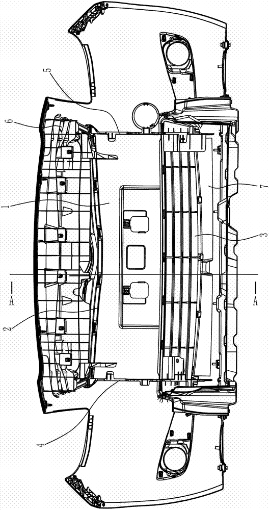
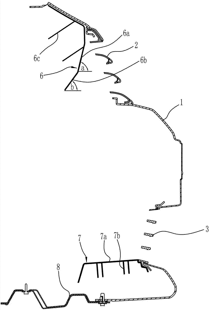
[0018] Such as figure 1 , figure 2 As shown, the present invention is composed of a front bumper 1, an upper grille 2, a lower grille 3, a left deflector 4, a right deflector 5, an upper deflector 6, and a lower deflector 7, etc. Wherein, the front bumper 1 is installed on the head of the passenger car, and an upper grille 2 and a lower grille 3 are provided on the front bumper 1, and the upper grille 2 is located above the lower grille 3; The bar 1 is also provided with a left deflector 4 and a right deflector 5, the left deflector 4 is located at the left end of the upper and lower grilles 2, 3, and the right deflector 5 is located at the upper and lower grilles 2, 3 Right end. The arrangement of the front bumper 1, the upper grille 2, the lower grille 3, the left air deflector 4, and the right air deflector 5 is the same as that of the prior art, and will not be ...


PUM


Abstract

The invention discloses a guide structure for a passenger vehicle head. An upper grid (2) and a lower grid (3) are arranged on a front bumper (1), the upper grid (2) is arranged above the lower grid (3), and a left guide plate (4) and a right guide plate (5) are further arranged in the front bumper (1). The left guide plate (4) is positioned at the left ends of the upper grid (2) and the lower grid (3), and the right guide plate (5) is positioned at the right ends of the upper grid (2) and the lower grid (3). An upper guide plate (6) is arranged behind the upper grid (2) transversely, and a lower guide plate (7) is arranged behind the lower grid (3) transversely. The upper guide plate (6), the lower guide plate (7), the upper grid (2) and the lower grid (3) define a square. By means of the guide structure, air entering the upper and lower grids can be guided to flow to a condenser and a radiator, and accordingly, not only the radiation efficiency of the condenser and the radiator is guaranteed, but also air eddies are effectively prevented, and the utilization ratio of motor output power is improved greatly.

Description

Technical field [0001] The invention belongs to the field of automobile technology, and specifically relates to a gas diversion structure of the front of a passenger car. Background technique [0002] The front bumper of the passenger car is provided with upper and lower grilles. When the passenger car is running, air enters the engine compartment through the upper and lower grilles to cool the condenser and radiator by air cooling. The shortcomings of the existing structure are: [0003] 1) The transverse ribs of the upper grille are generally inclined upward due to the requirements of the processing technology, so when the passenger car is driving, the intake air of the upper grille flows from low to high, so that a large part of the airflow will flow from the condenser The part of the airflow does not pass through the condenser and the radiator, which will affect the heat dissipation effect, especially when the upper grille is small, the position is higher, or the vehicle speed...

Claims


Application Information

Patent Timeline
Patent Type & Authority Applications(China)
IPC IPC(8): B60R19/52
Inventor 袁其文
Owner 力帆科技(集团)股份有限公司
Learn More