Trial paving device for stone paving and stone paving method

A stone and pavement technology, applied in roads, road repairs, roads, etc., can solve the problems of heavy weight, high cost of construction personnel, and large stone volume

Active Publication Date: 2020-10-20
济南园林开发建设集团有限公司
View PDF8 Cites 2 Cited by
  • Summary
  • Abstract
  • Description
  • Claims
  • Application Information

AI Technical Summary

Problems solved by technology

Because the stone is large in size and heavy in weight (for example, the stone used in squares and gardens generally weighs more than 50Kg), it takes a lot of effort for the construction personnel to move it. Moreover, once the construction personnel do not hold the stone tightly, the stone is easy to move. Injured construction workers

Method used


Image

  • Trial paving device for stone paving and stone paving method
  • Trial paving device for stone paving and stone paving method
  • Trial paving device for stone paving and stone paving method

Examples


Embodiment 1

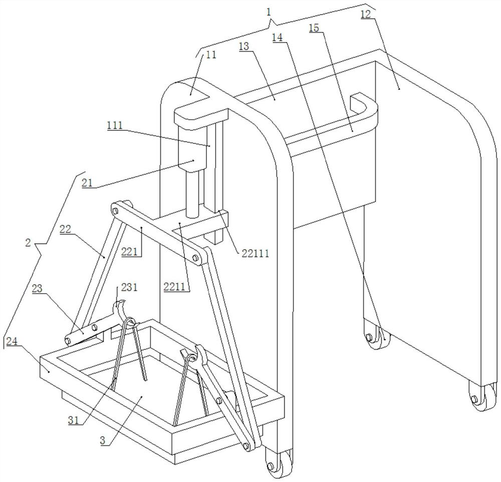
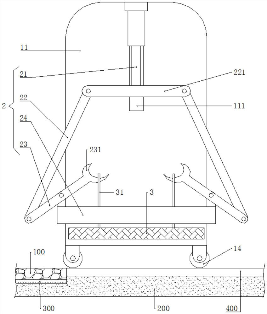
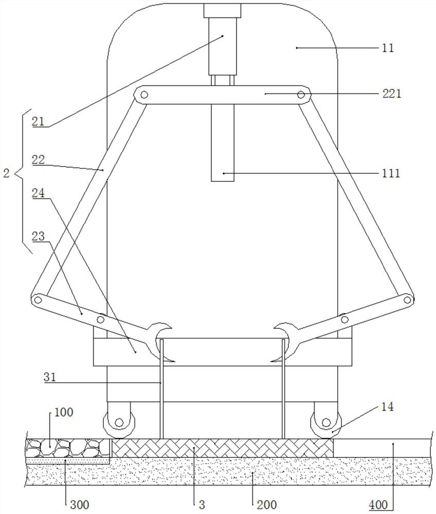
[0053] Such as figure 1 As shown, a trial paving device for stone paving includes a mobile frame 1, a clamping mechanism 2, and a template 3.

[0054] Such as figure 1 As shown, the mobile frame 1 includes a first mobile plate 11 , a second mobile plate 12 , a mobile connecting plate 13 , a mobile wheel 14 , and a mobile grab bar 15 . The first mobile plate 11 and the second mobile plate 12 are arranged side by side, and the mobile connection plate 13 is arranged between the first mobile plate 11 and the second mobile plate 12, and the first mobile plate 11 and the second mobile plate 12 are all connected to the mobile connection plate. 13 is welded and fixed, the lower end of the first mobile plate 11 and the lower end of the second mobile plate 12 are equipped with mobile wheels 14, and the upper end of the mobile connecting plate 13 is welded with a mobile grab bar 15.

[0055] Such as figure 1 As shown, the clamping mechanism 2 is disposed on the side of the first movin...

Embodiment 2

[0083] When paving the stone 100 according to the operation steps of Example 1, the construction personnel need to use a hammer to manually beat the template 3. This operation also increases the labor intensity of the construction personnel. Therefore, on the basis of Example 1, further Reduce the labor intensity of construction personnel.

[0084] In this regard, on the basis of Embodiment 1, this Embodiment 2 makes the following improvements:

[0085] Such as Figure 4 with Figure 5 As shown, a trial paving device for stone paving in the present embodiment 2 also includes a beating mechanism 4 . The beating mechanism 4 is arranged above the template 3 , and the beating mechanism 4 includes a reciprocating lifting assembly 41 and a hammer head 42 .

[0086] Such as Figure 4 with Figure 5 As shown, the reciprocating lifting assembly 41 includes a driving member 411 , a rotating shaft 412 , a turntable 413 , and a driving rod 414 . Driver 411 adopts motor, and the chas...


PUM


Abstract

The invention discloses a trial paving device for stone paving and a stone paving method, and relates to the technical field of stone paving. The trial paving device can utilize a clamping mechanism to lift or release a template. The stone paving method comprises the steps of (1) placing a template on a bonding layer in a virtual paving state by using a clamping mechanism, and hammering the template so as to enable the bonding layer in the virtual paving state to be compacted and flattened by the template; (2) lifting the template by using the clamping mechanism, continuously paving a bondinglayer in a virtual paving state on the bonding layer compacted and flattened by the template, placing the template on a new bonding layer in the virtual paving state by using the clamping mechanism, and hammering the template so as to enable the new bonding layer in the virtual paving state to be compacted and flattened by the template; (3) repeating the step (2) until the thickness of the bondinglayer compacted and flattened by the template reaches the designed thickness of the bonding layer; and (4) hammering the stone on the bonding layer compacted and flattened by the template. Accordingto the invention, the labor intensity of constructors can be reduced, and the safety risk can also be reduced.

Description

technical field [0001] The invention relates to the technical field of stone paving, in particular to a trial paving device for stone paving and a stone paving method. Background technique [0002] Stone is widely used to pave the ground in gardens and squares (such as railway station squares and airports). The construction steps of stone paving are as follows: [0003] (1) The construction personnel manually put the stone on the bonding layer in the state of virtual paving (when the construction personnel use cement mortar as the bonding material, the cement mortar layer is the bonding layer, and the cement mortar layer that has not been compacted and flattened That is, the cement mortar layer in the state of false paving, the cement mortar layer in the state of false paving is also the bonding layer in the state of false paving), the construction personnel beat the stone with a hammer, so that the bonding layer in the state of false paving is compacted and flattened by th...

Claims


Application Information

Patent Timeline
Patent Type & Authority Applications(China)
IPC IPC(8): E01C19/52
CPCE01C19/52
Inventor 刘飞甄蕾李爱倩
Owner 济南园林开发建设集团有限公司
Why Eureka
Try Eureka