
Hydraulic vibration damper

a technology of vibration damper and damper, which is applied in the direction of vibration damper, spring/damper, spring, etc., can solve the problems of inability to precisely set the movement between the open and closed position, the electromagnetic valve is open in the non-powered state, and the power requirement is large, etc., to achieve the effect of simple design, great damping force and easy adaptability to different application cases

Inactive Publication Date: 2009-12-03
THYSSENKRUPP BILSTEIN
View PDF5 Cites 9 Cited by
  • Summary
  • Abstract
  • Description
  • Claims
  • Application Information

AI Technical Summary

Benefits of technology

[0009]With this background, it is therefore an object of the invention to provide a controllable vibration damper that has a simple design and can easily be adapted to different application cases, guarantees great damping force and therefore safe driving behavior of the vehicle equipped with the vibration damper, in case of a power failure. This object is achieved by a hydraulic vibration damper, particularly for motor vehicles, having a cylinder that is filled with a damping medium, displaceably accommodates a working piston disposed on a piston rod, through which piston the damping medium can flow, and is divided, by the working piston, into a chamber on the piston rod side and a chamber away from the piston rod side.
[0013]According to the invention, the pressure prevailing in the pilot pressure chamber acts on a valve element of the main valve not directly, but by way of the pressure element, thereby making it possible to vary the hydraulically active surfaces for the opening and closing forces, independently of one another, to a great extent, in a particularly simple manner, when designing the vibration damper. The vibration damper is designed as a so-called pump-over system such that the setting valve module always has flow passing through it only in one direction, from the inflow opening to the outflow opening, because of the different flow-through resistance values of bottom valve and working piston and the volume change as the piston rod moves in and out.
[0014]The setting valve module can easily be joined together from individual parts, and appropriately adapted to the requirements by means of interchanging standardized parts, so that a desired damping characteristic is obtained. The slide can be displaced using extremely slight setting forces, so that a correspondingly weak configuration of the actuator is sufficient for changing the slide position, and a plunger coil arrangement can be used that is characterized by comparatively low power consumption, a low construction height, good controllability, and a low tendency to friction wear. In the non-powered state of the plunger coil arrangement, the pilot valve is moved into an emergency position by the slide spring, in which the pilot valve is closed. In the emergency position, a hard damping characteristic therefore occurs, which guarantees safe driving behavior.
[0018]The pressure element can act on the main valve, i.e. the valve element of the main valve, in a planar manner. In a preferred embodiment of the invention, the pressure element has at least one supporting edge or a supporting section, in order to guarantee a defined introduction of force from the pressure element to the main valve. Arranging a supporting edge or a supporting section on the pressure element is particularly advantageous in the case of an elastic configuration of the valve element of the main valve, for example a spring disk arrangement. Further possibilities for precisely adjusting the opening and closing behavior as well as the pressure-dependent progression of the flow-through rate result from the shape, the radial arrangement, and the progression of the at least one supporting edge or at least one supporting section. In particular, arranging at least one supporting edge or at least one supporting section guarantees a clearly defined and reproducible behavior of the main valve.

Problems solved by technology

Not only is there a great power requirement, but precise setting movements between the open and closed position are not possible, due to the design.
It is a further disadvantage that the electromagnetic valve is open in the non-powered state, and as a result, soft damping occurs.
In the case of a power failure, the soft damping of the vibration damper that then occurs can have unsafe driving behavior as a consequence.
An adaptation to different application cases, for example use in different motor vehicles, requires complicated changes in the design of the setting valve module.
The setting valve module is complicated in terms of its design.
It is a further disadvantage that the damping force is not defined, if, for example, a rotary drive that acts on the pilot valve fails due to a power failure.
In the end result, in the case of a technical defect of the rotary drive that acts on the pilot valve, an overly soft damping force of the vibration damper, and therefore unsafe driving behavior of the vehicle can result.

Method used


Image

  • Hydraulic vibration damper
  • Hydraulic vibration damper
  • Hydraulic vibration damper

Examples


Embodiment Construction

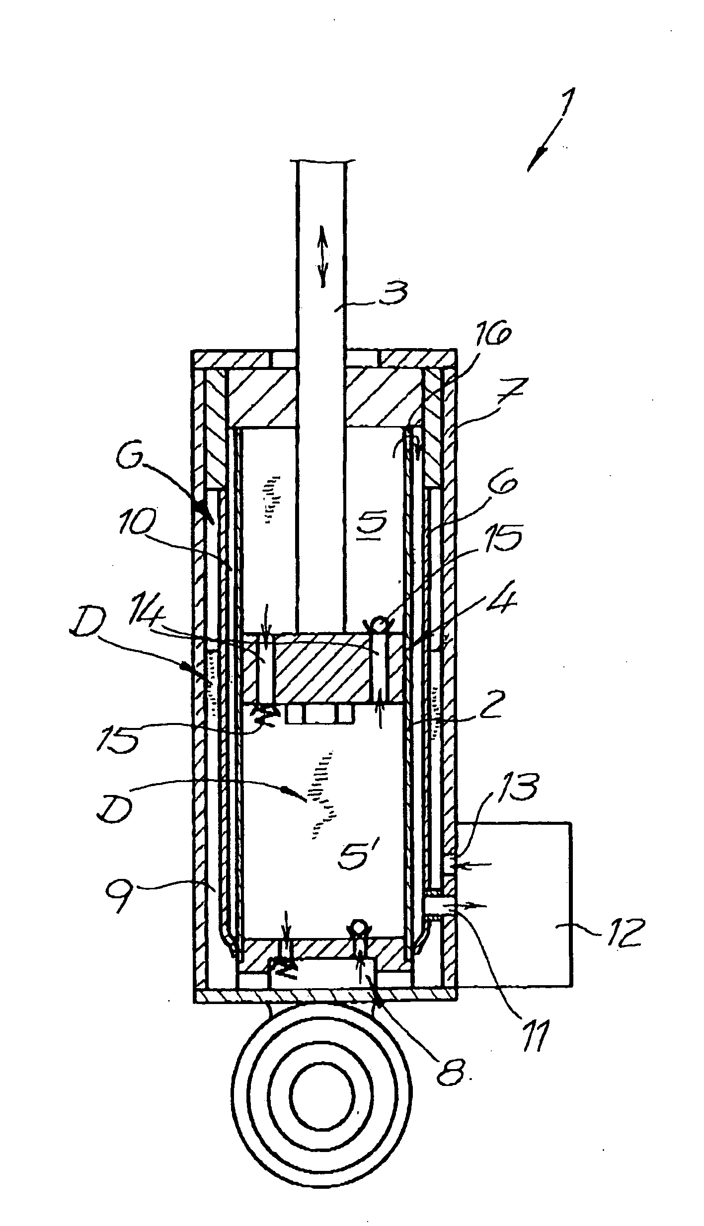
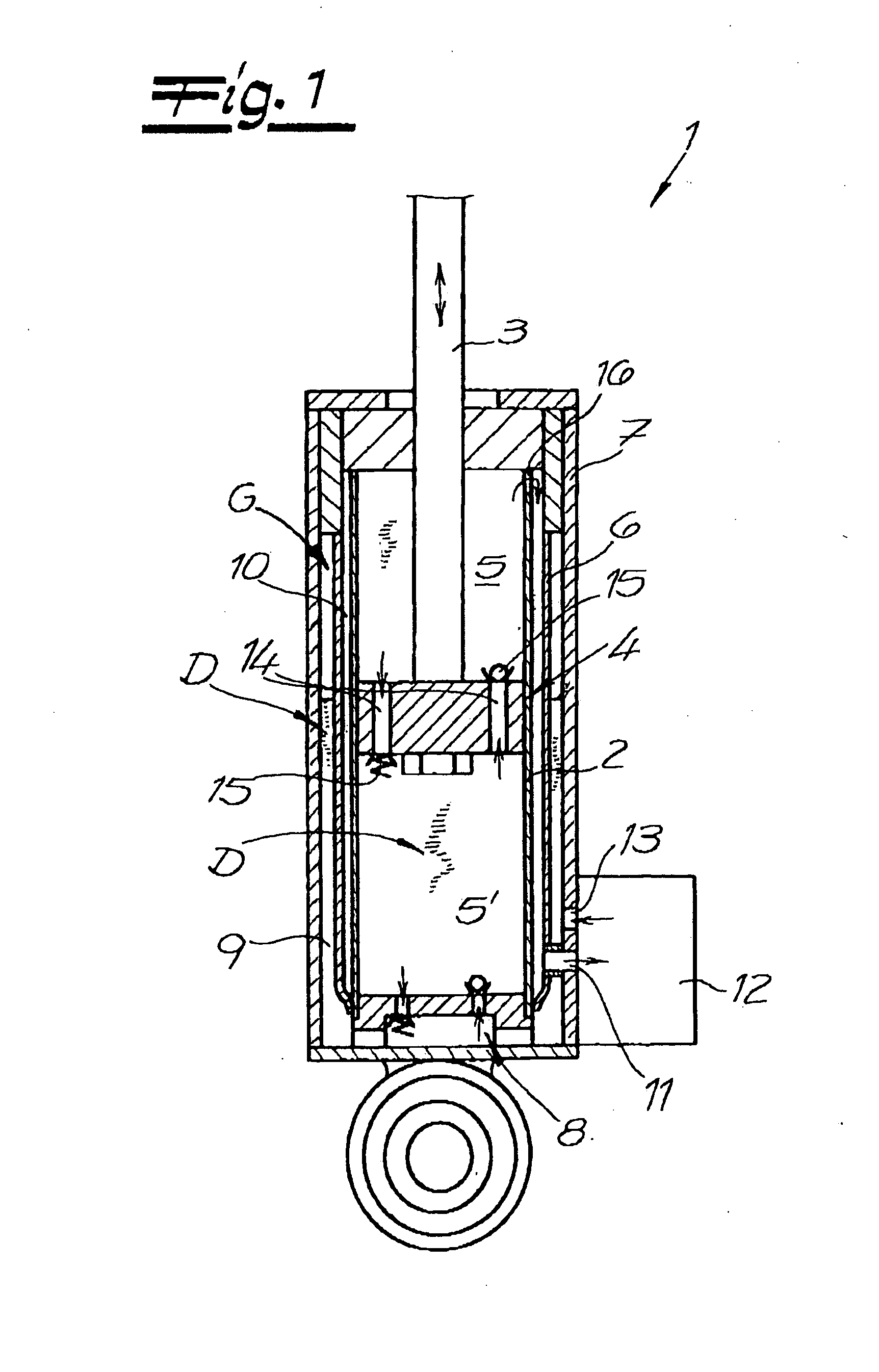
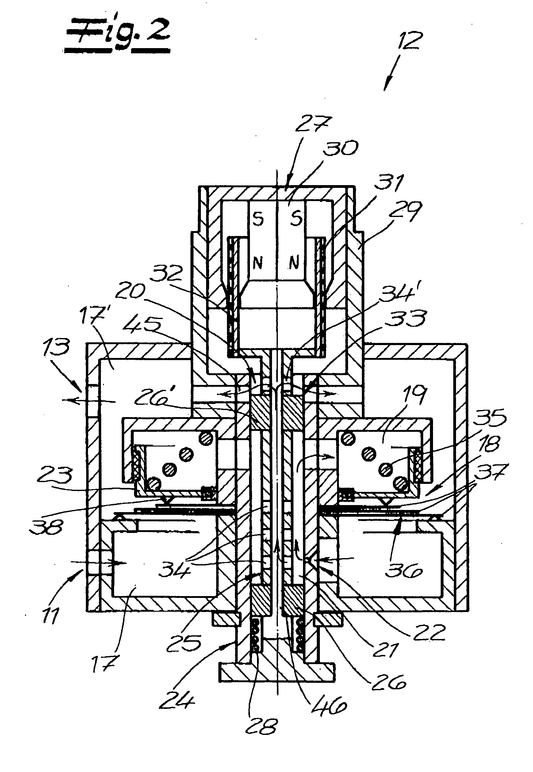
[0026]Referring now in detail to the drawings, FIG. 1 shows the structure of the vibration damper 1 according to the invention, having a cylinder 2 that is filled with a damping medium D, displaceably accommodates a working piston 4 disposed on a piston rod 3, through which piston damping medium D can flow, and is divided, by working piston 4, into a chamber 5 on the piston rod side and a chamber 5′ away from the piston rod side. Cylinder 2 is formed by an inner pipe that is surrounded by a center pipe 6 and an outer pipe 7. Chamber 5′ away from the piston rod side is connected with an equalization chamber 9 by way of a bottom valve 8 on cylinder 2, which chamber is formed between outer pipe 7 and center pipe 6. Equalization chamber 9 has a compressed gas G applied to it, and allows equalization of the volume in cylinder 2 that varies with the in and out movement of piston rod 3. Chamber 5 on the piston rod side is connected with inflow opening 11 of a controllable setting valve mod...


PUM


Abstract

A hydraulic vibration damper has a cylinder that is filled with a damping medium, displaceably accommodates a working piston disposed on a piston rod, through which the damping medium can flow, and is divided by the piston into two chambers. There is an equalization chamber that is connected with the working chamber, a pressure channel connected with the chamber on the piston rod side, and a controllable setting valve module connected with the pressure channel and the equalization chamber. The setting valve module has a pilot valve arrangement having a pilot pressure chamber and a pilot valve. The pilot pressure chamber is hydraulically separated from the main valve, and is connected with a valve chamber by a connection channel and at least one throttle point. A pressure element counteracts opening of the main valve, and pressure that acts on the main valve can be varied by the pilot valve.

Description

CROSS REFERENCE TO RELATED APPLICATIONS[0001]Applicant claims priority under 35 U.S.C. §119 of German Application No. 10 2007 005 288.1 filed Feb. 2, 2007.BACKGROUND OF THE INVENTION[0002]1. Field of the Invention[0003]The invention relates to a hydraulic vibration damper, particularly for motor vehicles, having a cylinder that is filled with a damping medium, displaceably accommodates a working piston disposed on a piston rod, through which piston the damping medium can flow, and is divided, by the working piston, into a chamber on the piston rod side and a chamber away from the piston rod side. There is an equalization chamber that is connected with the chamber away from the piston rod side, by way of a bottom valve, and a pressure channel connected with the chamber on the piston rod side. There is a controllable setting valve module, which is connected with the pressure channel by an inflow opening and with the equalization chamber by an outflow opening. here is a valve chamber o...

Claims


Application Information

Patent Timeline
Patent Type & Authority Applications(United States)
IPC IPC(8): F16F9/34F16F9/46
CPCF16F9/465
Inventor WEIMANN, CLAUS
Owner THYSSENKRUPP BILSTEIN
Learn More