Lighting apparatus and substrate having plurality of light-emitting elements mounted thereon and incorporated in this lighting apparatus

a technology of light-emitting elements and lighting apparatuses, which is applied in the direction of fixed installation, lighting and heating apparatus, lighting support devices, etc., can solve the problems of affecting the performance of electronic components, etc., to achieve the effect of reducing thermal deformation and stable performance for a long tim

Inactive Publication Date: 2009-12-03
TOSHIBA LIGHTING & TECH CORP +1
View PDF56 Cites 36 Cited by
  • Summary
  • Abstract
  • Description
  • Claims
  • Application Information

AI Technical Summary

Benefits of technology

[0010]It is an object of the present invention to provide a lighting apparatus which can suppress thermal deformation of a substrate having a plurality of light-emitting elements mounted thereon and demonstrate stable performance for a long time, and a substrate incorporated in this lighting apparatus.

Problems solved by technology

However, when the substrate is screwed into the apparatus main body at the plurality of positions as described above, the substrate gets distorted and deformed when the substrate thermally expands and thermally shrinks between the fixing positions.
When the substrate is deformed in this manner, a soldered portion to which an electronic component is secured may be cracked or the tight connection of the substrate with respect to the apparatus main body may be degraded in some cases.
When the tight connection of the substrate is degraded, heat radiation of the substrate cannot be sufficiently performed, and the substrate is further deformed.
However, in the structure depicted in this Patent Document, when linear expansion coefficients of the substrate, the reinforcing member, and the sealing member are different from each other, warpage or deformation occurs in the substrate increasingly.
Therefore, selecting materials for the respective members is difficult.
If the reinforcing structure disclosed in this Patent Document is adopted for the substrate in the lighting apparatus having the plurality of light-emitting elements mounted thereon, thermal deformation of the substrate cannot be effectively avoided.

Method used


Image

  • Lighting apparatus and substrate having plurality of light-emitting elements mounted thereon and incorporated in this lighting apparatus
  • Lighting apparatus and substrate having plurality of light-emitting elements mounted thereon and incorporated in this lighting apparatus
  • Lighting apparatus and substrate having plurality of light-emitting elements mounted thereon and incorporated in this lighting apparatus

Examples


first embodiment

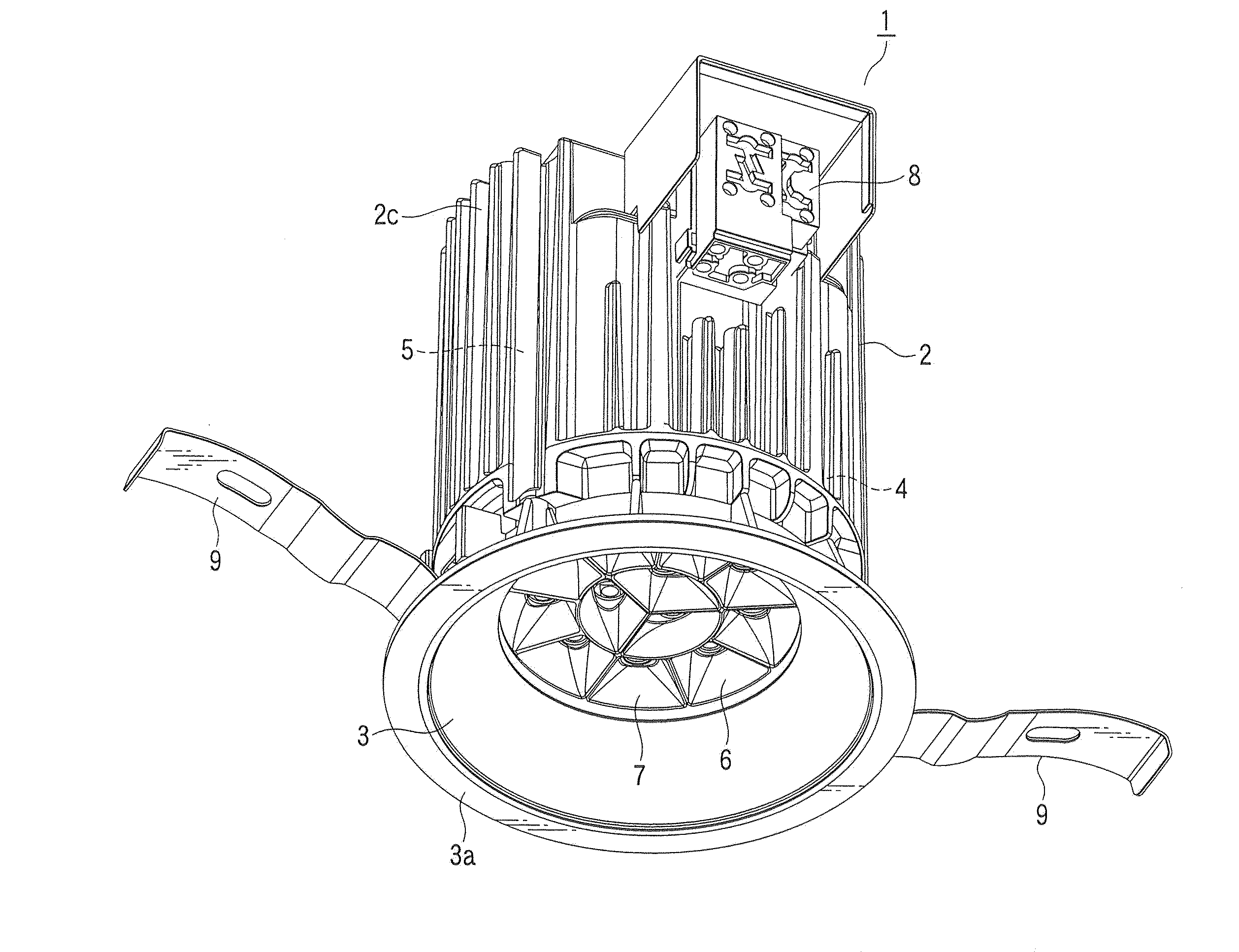
[0029]A substrate and lighting apparatus according to the present invention will be described with reference to FIGS. 1 to 6. As an example of the lighting apparatus, the case where the present invention is applied to a down light 1 will be discussed.

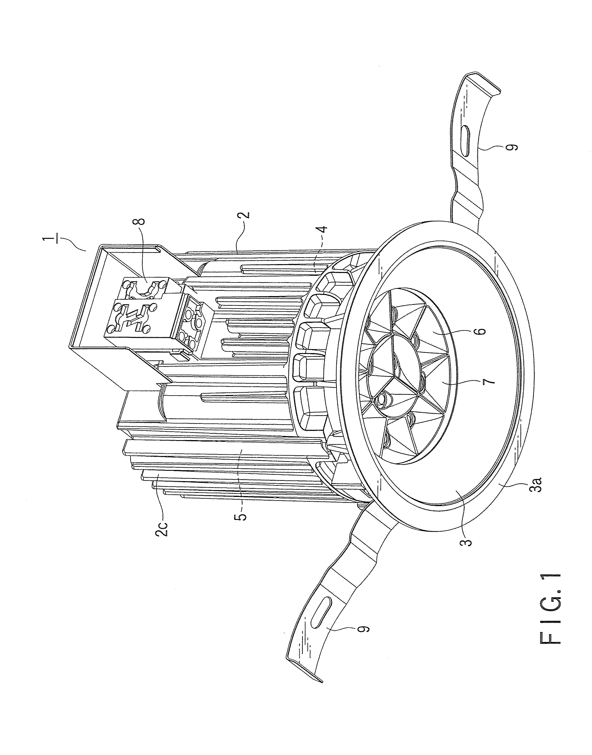
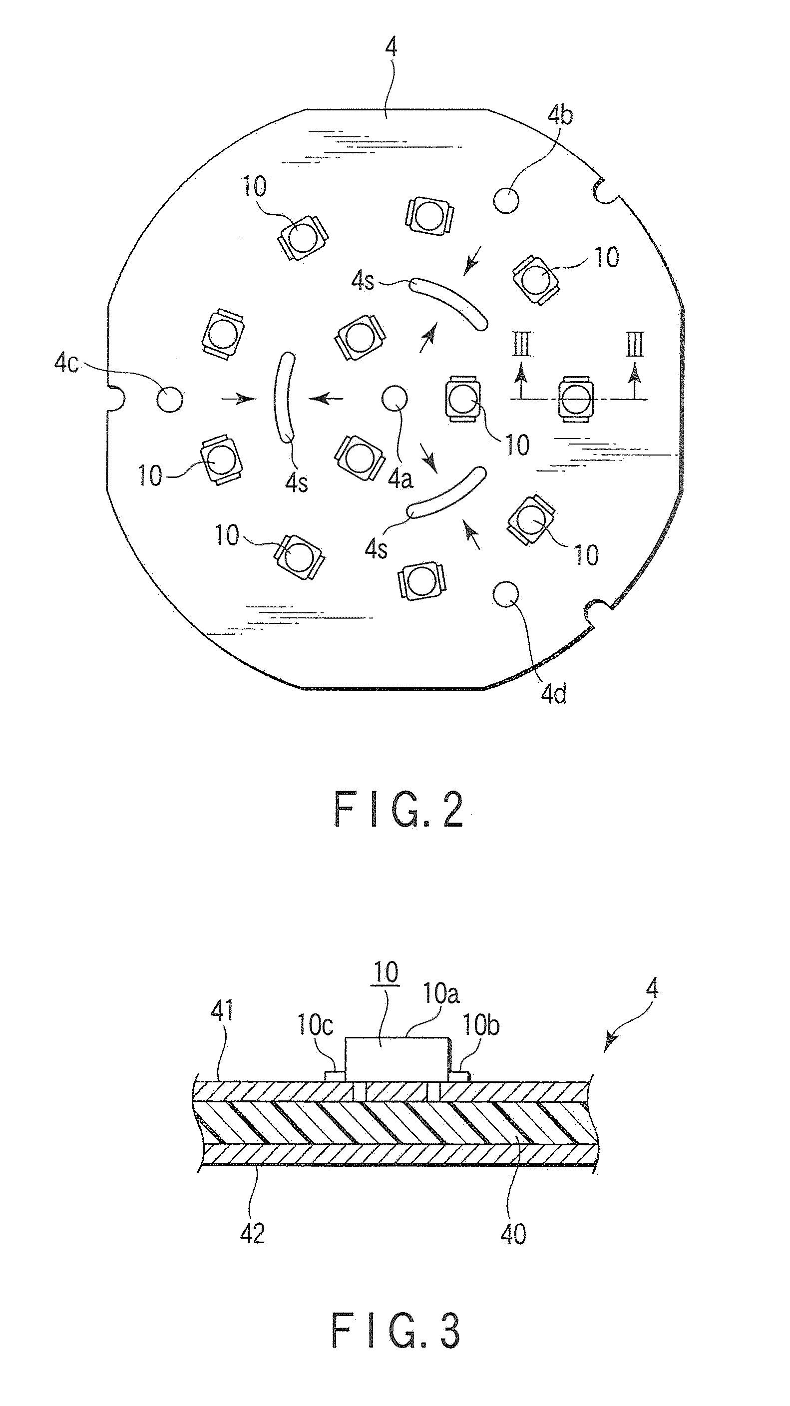
[0030]FIG. 1 is a perspective view of the down light 1, FIG. 2 is a view showing a substrate 4 incorporated in the down light 1 as seen from a front surface side thereof, FIG. 3 is a partially enlarged cross-sectional view showing the substrate 4 in FIG. 2 taken along a line III-III, FIG. 4 is a view showing a reflector 6 incorporated in the down light 1 in FIG. 1 as seen from the front surface side thereof, FIG. 5 is a cross-sectional view of the reflector 6 in FIG. 4 taken along a line V-V, and FIG. 6 is a partially enlarged cross-sectional view showing a primary part of the down light 1 in FIG. 1 in a partially enlarged manner.

[0031]As light-emitting elements serving as the light source of the down light 1, solid-state light-emitting...

third embodiment

[0069]A substrate 4 according to the present invention will now be described with reference to FIG. 8. FIG. 8 is a view showing the substrate 4 from a front surface side and corresponds to FIGS. 2 and 7 of the respective embodiments. In this example, like reference numerals likewise denote constituent elements having the same functions as those in the foregoing embodiments, thereby omitting a detailed explanation thereof.

[0070]The substrate according to this embodiment is different from those of the foregoing embodiments in that a screw through hole 4a at a central portion of the substrate 4 is omitted and three slits 4s-3 having different shape and directions are provided. That is, each of the slits 4s-3 is provided at a substantially central part of each side of an imaginary regular triangle connecting three screw through holes 4b, 4c and 4d formed in the substrate 4 in such a manner that each slit becomes substantially orthogonal to each side.

[0071]In this embodiment, since the s...

fourth embodiment

[0073]FIG. 9 is a view showing a substrate 4 according to the present invention from a front surface side. In this embodiment, screw through holes 4b, 4c, 4d and 4e are formed at four positions in a peripheral portion of the substrate 4 at equal intervals, and each of substantially rectangular slits 4s-4 is formed on each side of an imaginary square connecting these four holes. It is to be noted that, although not shown, a slit may be formed on each diagonal line connecting the screw through holes 4b and 4d or the screw through holes 4c and 4e.

[0074]In this embodiment, the same effects as those in the foregoing embodiments can be demonstrated, and concentration of stress caused due to thermal expansion of the substrate 4 can be avoided, whereby warpage or deformation of the substrate 4 can be suppressed.

[0075]FIG. 10 is a view showing a substrate 4 according to a fifth embodiment of the present invention from a front surface side. The substrate 4 according to this embodiment has su...


PUM


Abstract

The present invention provides a down light include a thermally-conductive main body, and a substrate which is mounted on this main body through a plurality of screw, has slits which are formed on straight lines connecting the screw with each other in directions orthogonal to the straight lines, and has a plurality of LEDs arranged thereon.

Description

CROSS-REFERENCE TO RELATED APPLICATIONS[0001]This application is based upon and claims the benefit of priority from prior Japanese Patent Applications No. 2008-142063, filed May 30, 2008; and No. 2009-071276, filed Mar. 24, 2009, the entire contents of both of which are incorporated herein by reference.BACKGROUND OF THE INVENTION[0002]The present invention relates to a substrate having a plurality of light-emitting elements such as LEDs mounted thereon and to a lighting apparatus having this substrate incorporated in an apparatus main body.[0003]Recently, lighting apparatus which uses a plurality of light-emitting elements such as LEDs as light sources have been developed. For lighting apparatus of this type, a demand of a high output is increasing, and there is a tendency that the number of light-emitting elements employed is also increasing.[0004]The plurality of light-emitting elements are mounted on the substrate and incorporated into an apparatus main body. The substrate is sub...

Claims


Application Information

Patent Timeline
Patent Type & Authority Applications(United States)
IPC IPC(8): F21V29/00F21V19/00F21V29/505
CPCF21S8/026F21V17/12F21V19/0055F21Y2101/02H05K1/0206H05K1/0271F21V21/00H05K2201/10106H05K2201/10409H05K2201/10598F21V19/0035F21V29/00F21V29/004H05K2201/09063F21Y2115/10F21V29/74F21V29/50
Inventor MORIYAMA, TAKAYOSHIHIGUCHI, KAZUNARIHASHIMOTO, SUMIOKUMASHIRO, SHINICHI
Owner TOSHIBA LIGHTING & TECH CORP
Why Eureka
Try Eureka