Image heating apparatus

a heating apparatus and image technology, applied in the field of image heating apparatus, can solve the problems of uneven glossiness, uneven layer, etc., and achieve the effect of avoiding a shortened life of roughening surfa

Inactive Publication Date: 2009-12-03
CANON KK
View PDF0 Cites 48 Cited by
  • Summary
  • Abstract
  • Description
  • Claims
  • Application Information

AI Technical Summary

Benefits of technology

[0023]A principal object of the present invention is to solve a problem, that damage of a fixing member surface is transferred onto a toner image to cause uneven glossiness on the toner image after fixation, while avoiding a shortened lifetime of the roughening surface.

Problems solved by technology

However, a surface layer of the fixing member is accompanied with a problem such that the layer is gradually roughened due to attack by sheet passing or due to contamination such as paper powder or offset toner.
When the surface state of the fixing member is different, a difference in surface state correspondingly occurs on the toner image, with the result that uneven glossiness occurs.
However, when a fixing speed is increased and a recording material on which a solid image is formed is subjected to the fixation, it is found that the following problem occurs.
This is because the glossiness of the toner is liable to be affected by the smoothness of the recording material surface.
As described above, in the case where the conveying speed of the recording material is high, the lower layer-side toner of the toner image is not sufficiently heated.

Method used


Image

  • Image heating apparatus
  • Image heating apparatus
  • Image heating apparatus

Examples


embodiment 1

(1) Image Forming Apparatus

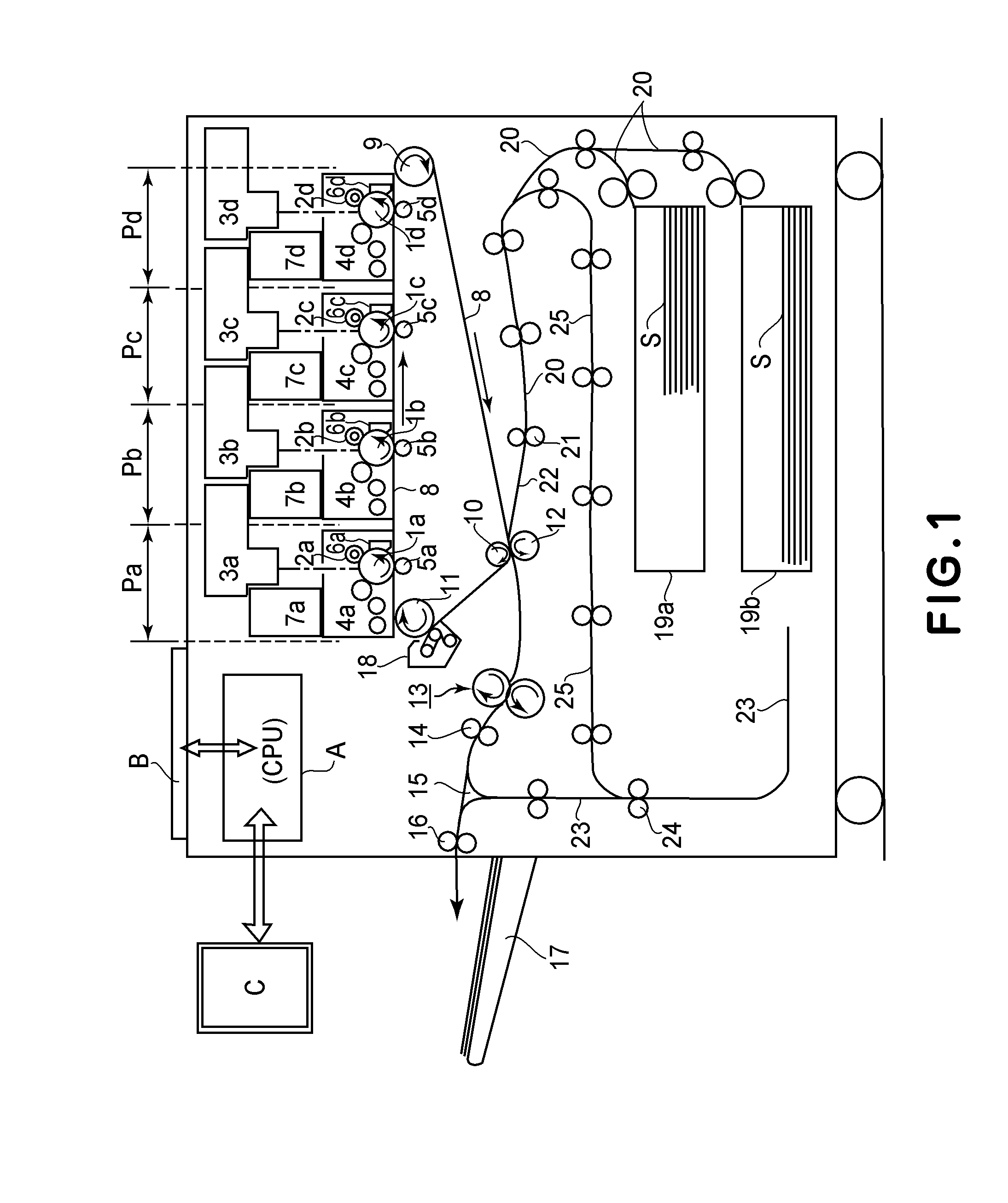
[0046]FIG. 1 is a schematic structural view of an embodiment of an image forming apparatus in which a heating apparatus (device) according to the present invention is mounted as a fixing device. This image forming apparatus is a full-color laser beam printer of an electrophotographic type wherein an image corresponding to electrical image information inputted from a host apparatus C such as a personal computer or an image reader to a controller (control means: CPU) A is formed on a recording material (transfer paper) S and is outputted. The controller A sends and receives various pieces of the electrical image information between the controller A and the host apparatus C or an operating display portion (operating portion) B and effects centralized control of an image forming operation of the image forming apparatus in accordance with a predetermined control program or a reference table.

[0047]In the apparatus, first to fourth image forming stations P (Pa, P...

embodiment 2

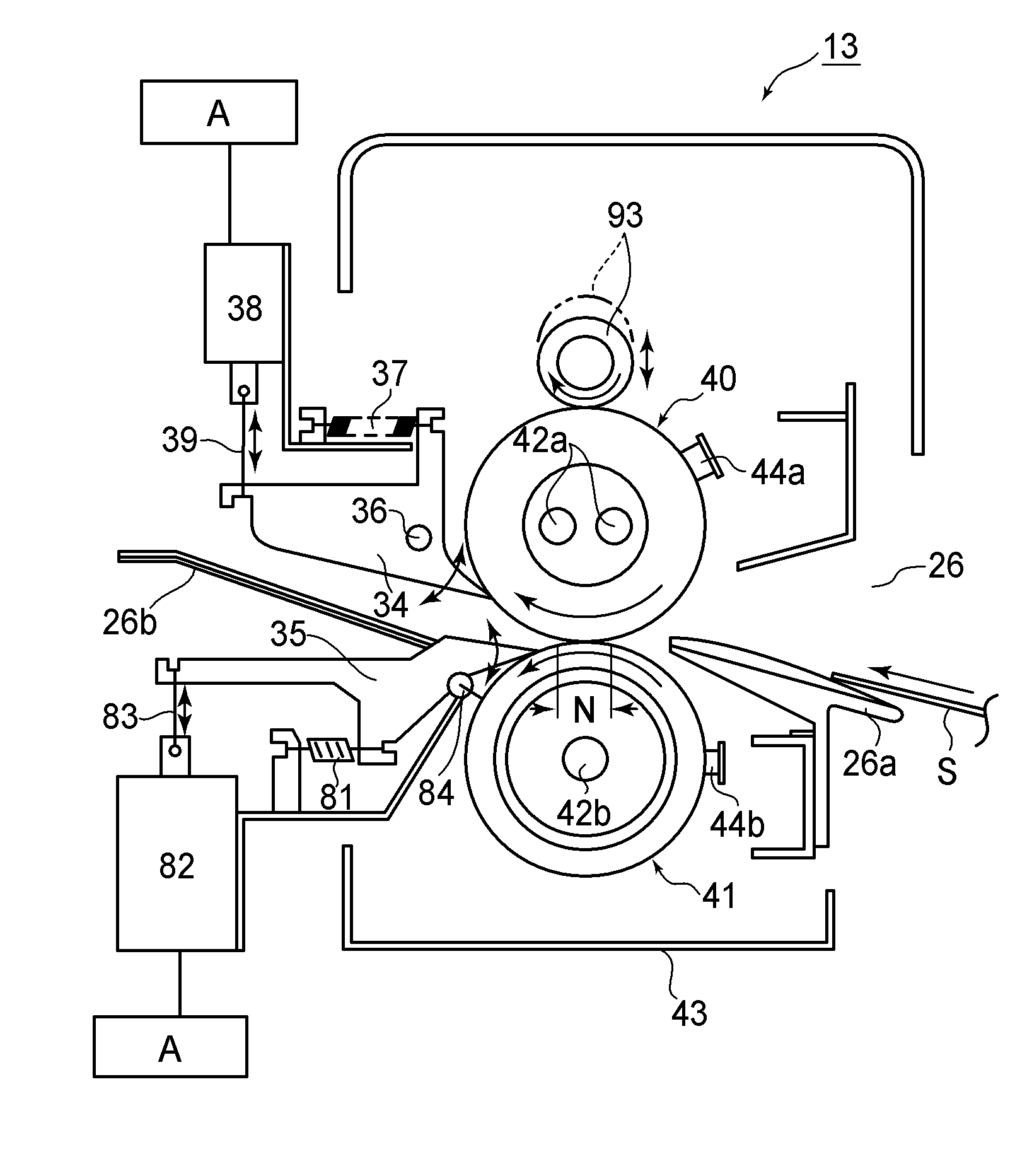
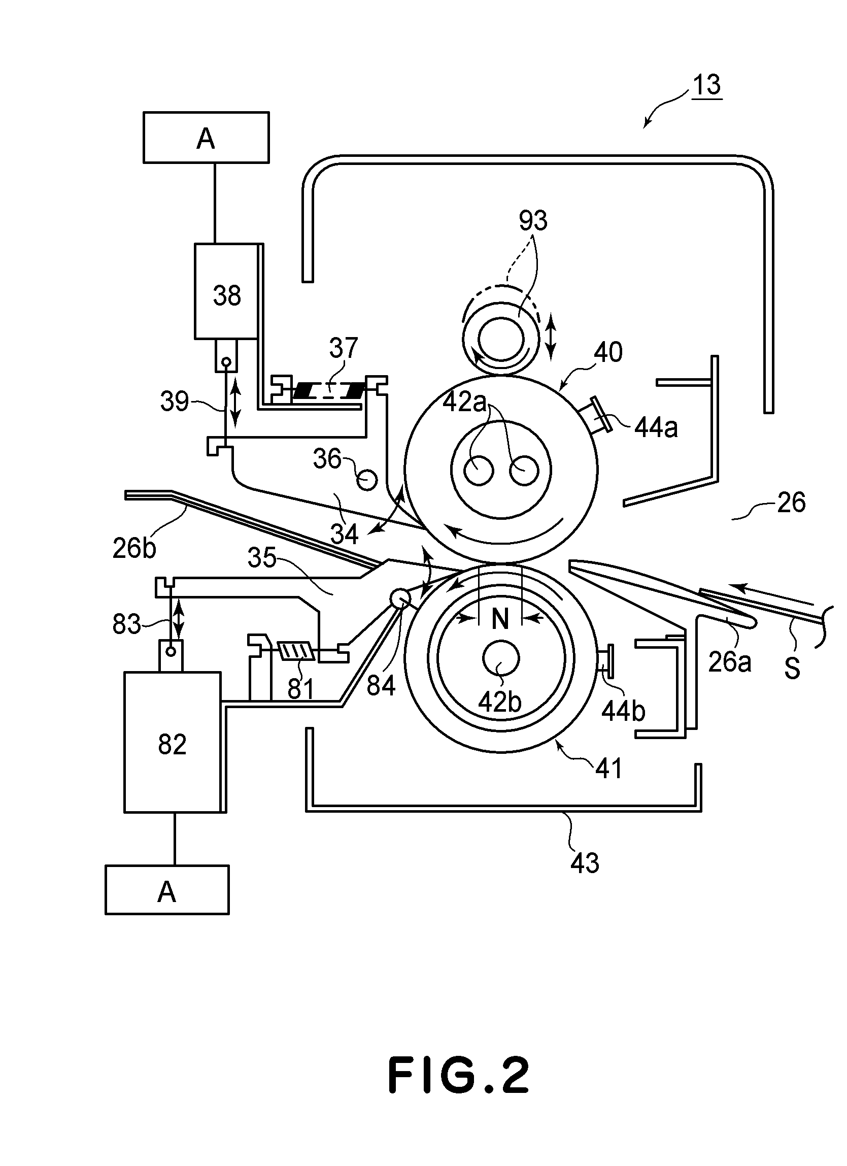
[0116]Embodiment 2 will be described with reference to FIG. 11. In recent years, an image forming apparatus capable of printing out the recording material S subjected to both-side-printing has been generally used. For that reason, in the case where both side images are intended to be fixed on the recording material, the separation claw trace (by the separation claw 35) left on the surface of the pressing roller 41 is also transferred onto the toner images on the thick paper when the thick paper is passed through the fixing nip at high speed.

[0117]For that reason, similarly as in Embodiment 1, a roughening roller 80 for movement toward and away from the pressing roller 41 may be provided on the pressing roller 41 side. Further, the lower separation claw 35 may also be provided similarly so as to be movable toward and away from the pressing roller 41. As the roughening roller 80, a member having the same constitution as that of the roughening roller 93 for roughening the fixing roller...

embodiment 3

[0125]As described above, when the recording material conveying speed is increased, the surface transfer property is enhanced. In the state in which the surface transfer property is enhanced, the glossiness of the toner images after the fixation is enhanced.

[0126]Further, in the case where the toner images are formed on both sides of the recording material, the glossiness of the toner images formed on the recording material surface after second passing of the recording material through the fixing nip is higher than that after first passing of the recording material through the fixing nip. This is because the toner images formed on the recording material surface are heated again by the pressing roller 41 during the second passing of the recording material through the fixing nip. When the glossiness of the toner images is increased, the separation claw trace (by the separation claw 35) left on the surface of the pressing roller 41 is more visible. Further, a difference in glossiness b...


PUM


Abstract

An image heating apparatus includes a heating member for heating a toner image on a recording material in a heating nip; a pressing member for forming the heating nip in contact with the heating member; a abrading member for abrading a surface of the heating member; a contact-and-separation device for permitting contact and separation of the abrading member with respect to the heating member; and a selecting device for selecting, depending on a basis weight of the recording material to be heated by said heating member, whether or not the contact-and-separation means brings the abrading member into contact with the pressing member before a recording material is conveyed to the heating nip.

Description

FIELD OF THE INVENTION AND RELATED ART[0001]The present invention relates to an image heating apparatus (device) suitably used as an image heat-fixing device to be mounted in an image forming apparatus, such as a copying machine, a facsimile machine, or a printer, for forming a toner image on a recording material by an electrophotographic method an electrostatic recording method, a magnetic recording method, or the like.[0002]As a heating-type image fixing device in an image forming apparatus of an electrophotographic type, a fixing device for heat-fixing the toner image in a fixing nip in which a fixing member and a pressing member contact each other has been used conventionally.[0003]However, a surface layer of the fixing member is accompanied with a problem such that the layer is gradually roughened due to attack by sheet passing or due to contamination such as paper powder or offset toner. Particularly, when a large number of sheets of the recording material is caused to pass th...

Claims


Application Information

Patent Timeline
Patent Type & Authority Applications(United States)
IPC IPC(8): G03G15/20
CPCG03G15/5029G03G15/2025G03G15/2028G03G2215/00738
Inventor KAMEDA, SEIICHIRO
Owner CANON KK
Why Eureka
Try Eureka