System for assembling two rotary parts together by flanges

Inactive Publication Date: 2009-12-03
SN DETUDE & DE CONSTR DE MOTEURS DAVIATION S N E C M A
View PDF31 Cites 25 Cited by
  • Summary
  • Abstract
  • Description
  • Claims
  • Application Information

AI Technical Summary

Benefits of technology

[0027]In this way, the invention establishes a mechanical connection by compression between the first segment of the bolt and the cylindrical passage, thereby making it possible, while transferring rotor torque, to avoid any movement between the bolt and the flanges, and in particular any shearing. Because of this local compression stress, fatigue phenomena are limited, as is the initiation of fatigue cracking in the material constituting said flanges.
[0028]The strength, and thus the lifetime, of the bolt is thus significantly improved, but without that requiring the bolt to be overdimensioned.
[0029]The invention also serves to lengthen the lifetime of the flanges, so it is possible to envisage implementing simpler forging ranges and/or reducing the size of the forging blanks since a metallurgical structure close to that of the skin of the forging

Problems solved by technology

Furthermore, because the fit between each of the bolts 40 and the corresponding cylindrical passage 30 is not identical in all cases, forces are distributed unequa

Method used


Image

  • System for assembling two rotary parts together by flanges
  • System for assembling two rotary parts together by flanges
  • System for assembling two rotary parts together by flanges

Examples


Embodiment Construction

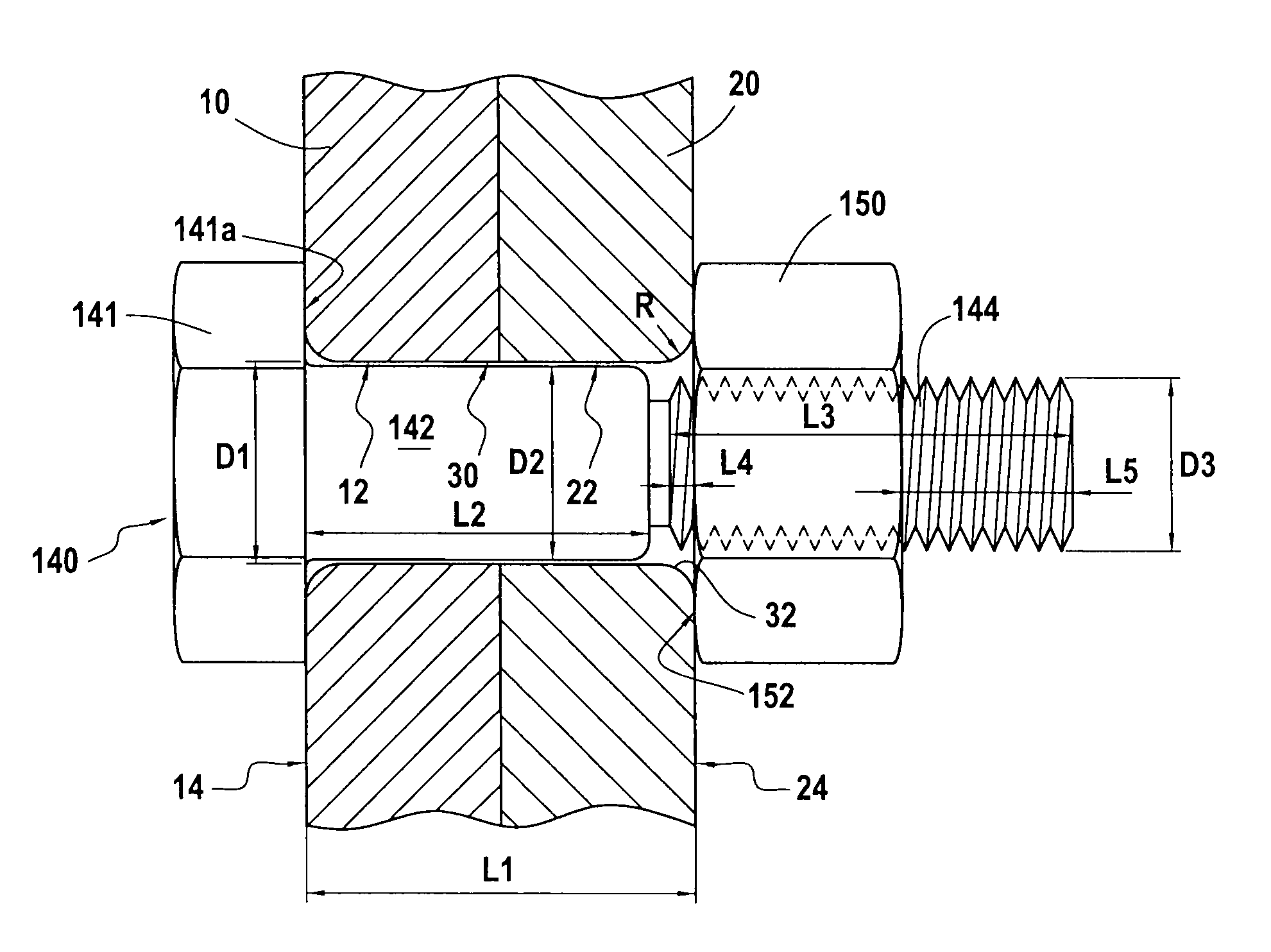
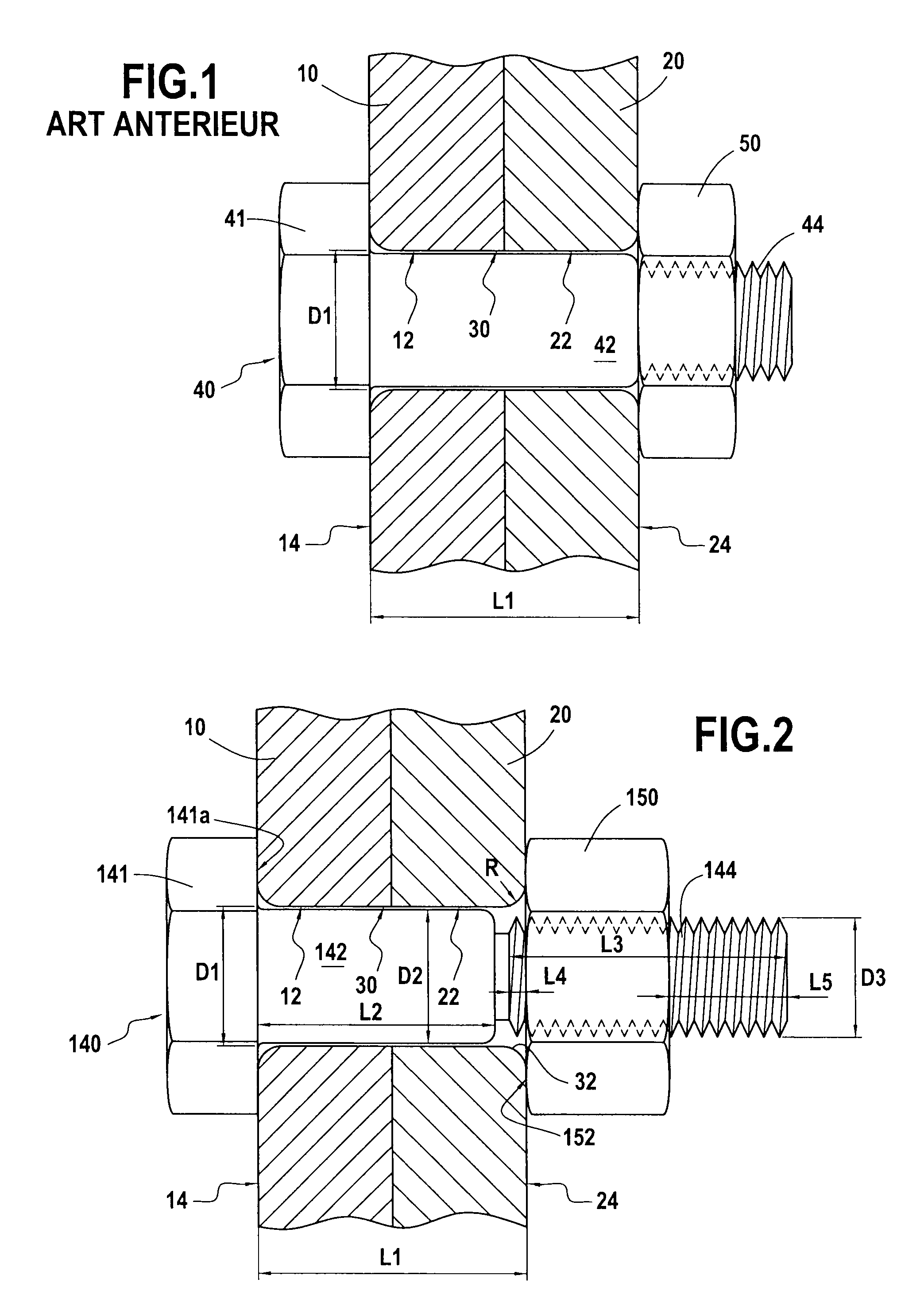
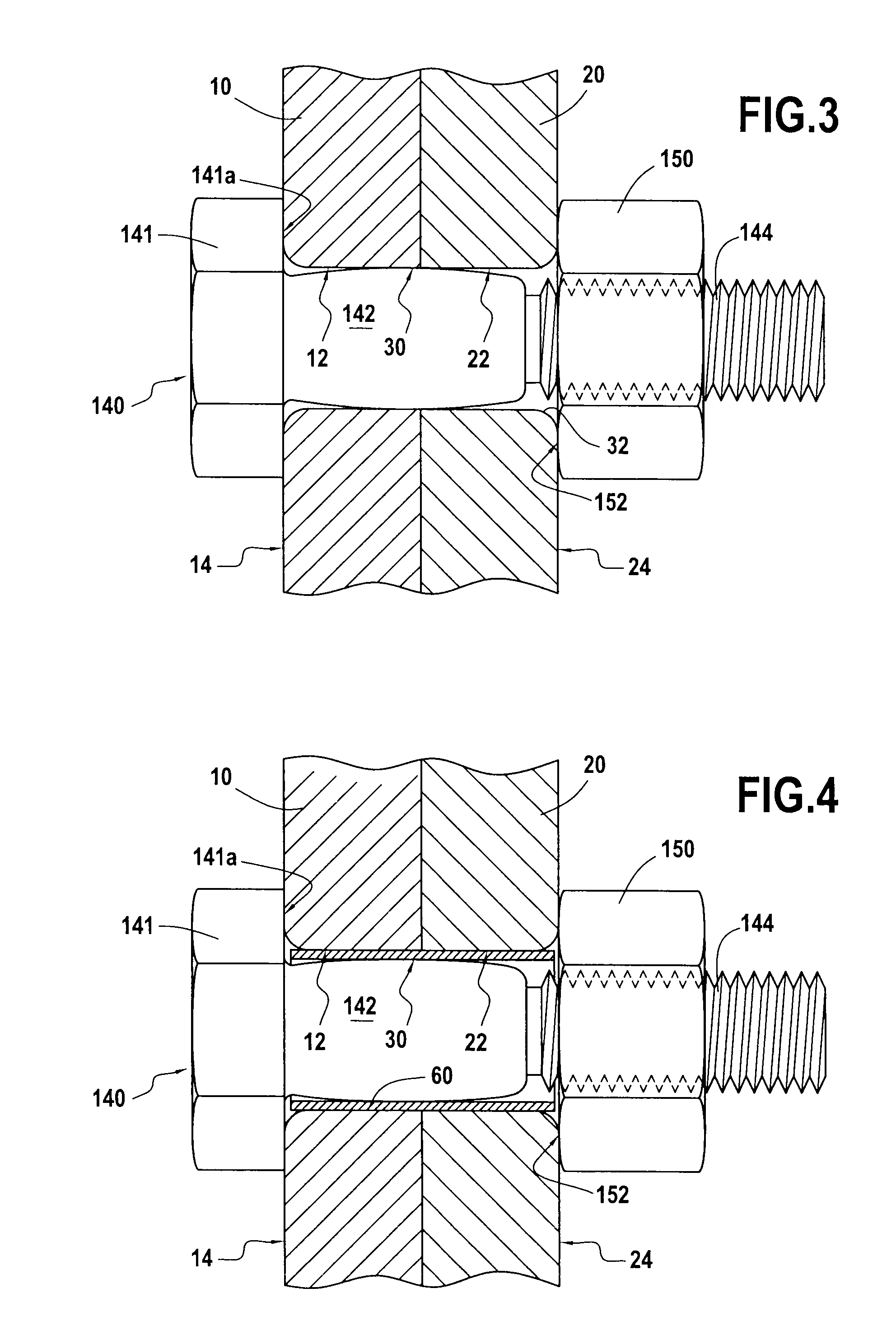
[0038]As can be seen in FIG. 2, use is made in the invention of a bolt 140 that is configured in a special way for the purpose of assembling together the flanges 10 and 20 via their assembly holes 12 and 22 placed in register to form the cylindrical passage 30.

[0039]The head 141 of the bolt is flat, and has a plane bearing face 141a that faces towards the shank of the bolt and that is suitable for coming into contact against the outside face 14 of the first flange 10.

[0040]The shank of the bolt 140 comprises a first segment 142 of length L2 that extends the head 141 and that is designed to be received in the cylindrical passage 30 of diameter D1, followed by a second segment 144 of length L3 that extends the first segment 142 and that is threaded.

[0041]In characteristic manner, the first segment 142 presents a maximum diameter D2>D1 so as to constitute positive interference when the first segment 142 is placed in the cylindrical passage 30.

[0042]Provision is made for the maximum dia...


PUM


Abstract

The invention relates to a system of assembling together two rotary parts by means of flanges, said flanges forming a cylindrical passage of diameter D1 and of length L1.
In characteristic manner, the system comprises:
    • a bolt having a head and a shank that presents a first segment and a second segment that is threaded, said first segment presenting a maximum diameter D2 that is greater than D1; and
    • a nut of thread suitable for co-operating with the threaded second segment and presenting a plane first face suitable for bearing against the outside face of the second flange, whereby the first segment is caused to engage tightly in the cylindrical passage and the two parts are secured to each other by tightening the nut on the threaded second segment.

Description

[0001]The invention relates to a system for assembling two rotary parts together by flanges.BACKGROUND OF THE INVENTION [0002]Said flanges are annular or scalloped and they include assembly holes. The first flange is suitable for being pressed against the second flange so that a hole in the first flange comes into alignment with a hole in the second flange, thereby forming a cylindrical passage of diameter D1 and length L1.[0003]Such cylindrical passages are thus regularly spaced apart around the circumference of the two flanges for assembling together, and for each of these cylindrical passages it is necessary to put fastener means into place for tightly assembling together the two rotary parts that are to be secured one to the other.[0004]For this purpose, an assembly of the kind shown in FIG. 1 is generally used: the cylindrical passage 30 going through both flanges 10 and 20 receives a smooth first segment 42 of the shank of a bolt 40. The shank of the bolt 40 includes, at its e...

Claims


Application Information

Patent Timeline
IPC IPC(8): F16D1/033
CPCF16B5/02F16B19/02Y10T403/645F16D1/033F16D1/076F16B35/041F16B2200/506
Inventor MONS, CLAUDE MARCEL
Owner SN DETUDE & DE CONSTR DE MOTEURS DAVIATION S N E C M A
Why Eureka
Try Eureka