Power transmission line section

a technology of power transmission line and section, which is applied in the direction of couplings, mechanical equipment, drilling pipes, etc., can solve the problems of rotor rotation within the stator, limited torque transmission capability and fatigue life, and articulating ends of the power transmission section can quickly wear ou

Inactive Publication Date: 2009-12-03
WALL KEVIN W +1
View PDF32 Cites 19 Cited by
  • Summary
  • Abstract
  • Description
  • Claims
  • Application Information

AI Technical Summary

Benefits of technology

[0009]Briefly stated, in accordance with one aspect of the present invention, a rotational power transmission section is provided that includes an input component having a central axis for connection with a source of rotational power that provides input torque to the input component, and an output component having a central axis for connection with a driven member to provide output torque to the driven member. A connecting shaft having a longitudinal axis extends between and rotationally interconnects the input component with the output component for transmitting torque between the input component and the output component. The shaft is connected with each of the input component and the output component by a ball joint to allow swiveling motion between the shaft ends and each of the input component and the output component, and to allow angular deflection of the longitudinal axis of the shaft relative to the longitudinal axes of each of the input and output components.

Problems solved by technology

When drilling mud is pumped downhole under pressure to and through the mud motor, the result is that the downwardly moving drilling mud causes the rotor to rotate within the stator.
Although a number of different articulating power transmission section arrangements have been disclosed and utilized in downhole drilling systems, many have been limited in their torque transmission capability and in their fatigue life.
Additionally, the drilling mud that is utilized to drive the mud motor is of an abrasive nature, and unless they are adequately protected from the drilling mud the articulating ends of the power transmission section can quickly wear, requiring frequent drill string shutdowns for replacement of power transmission section components.

Method used


Image

  • Power transmission line section
  • Power transmission line section
  • Power transmission line section

Examples


Embodiment Construction

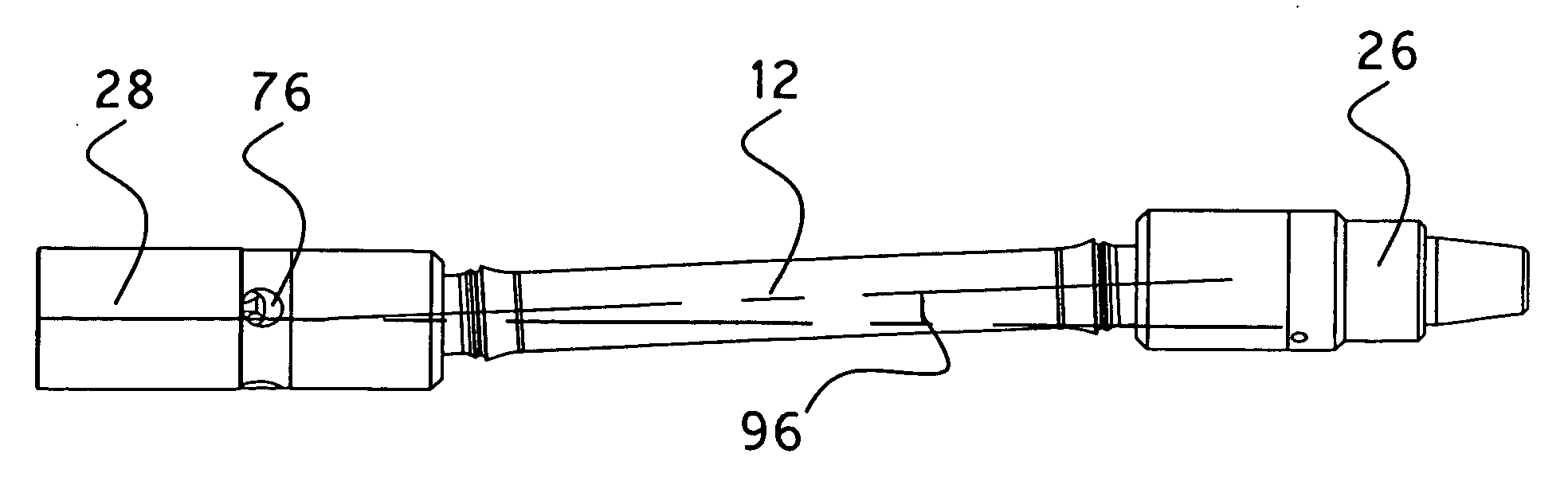
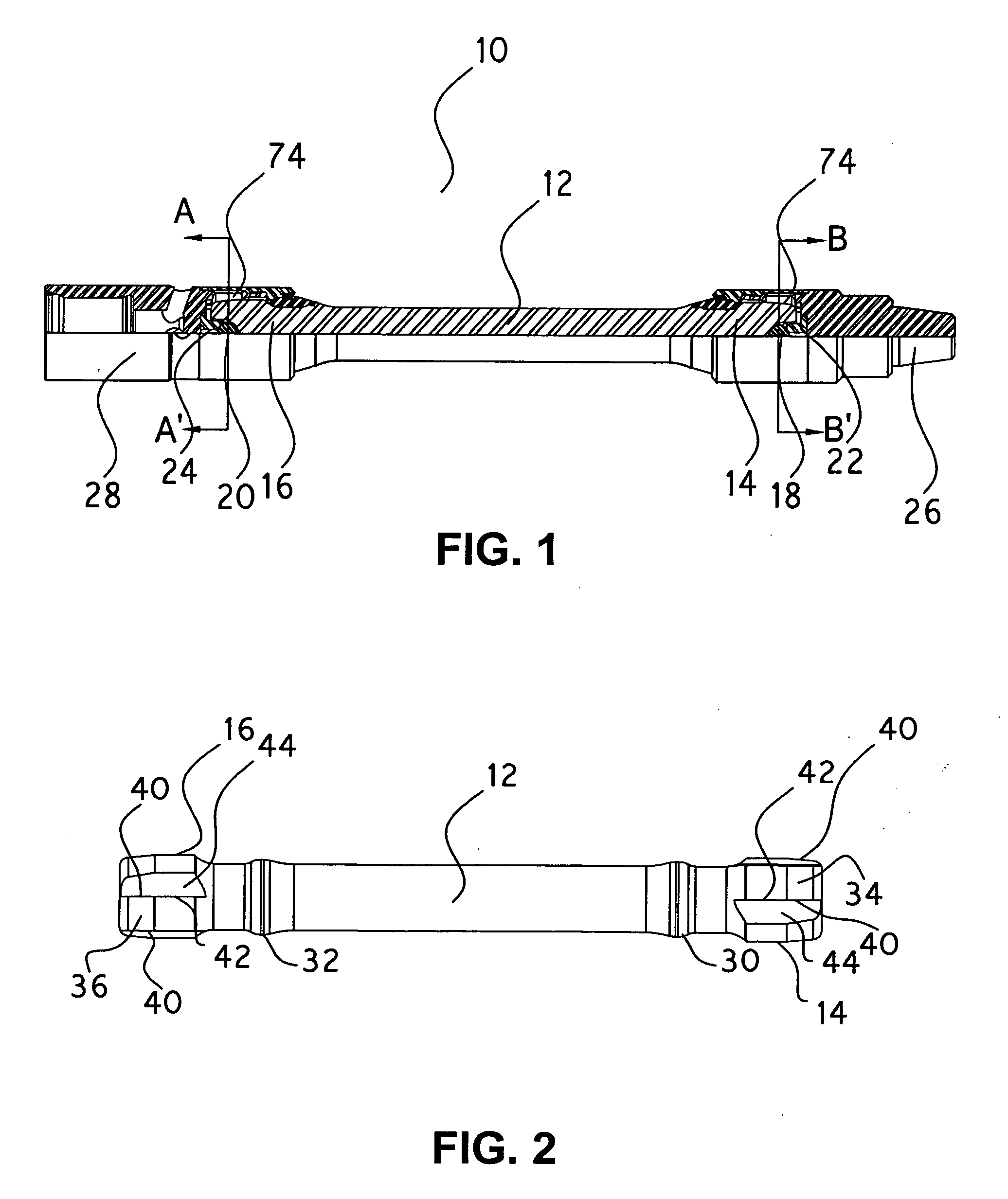
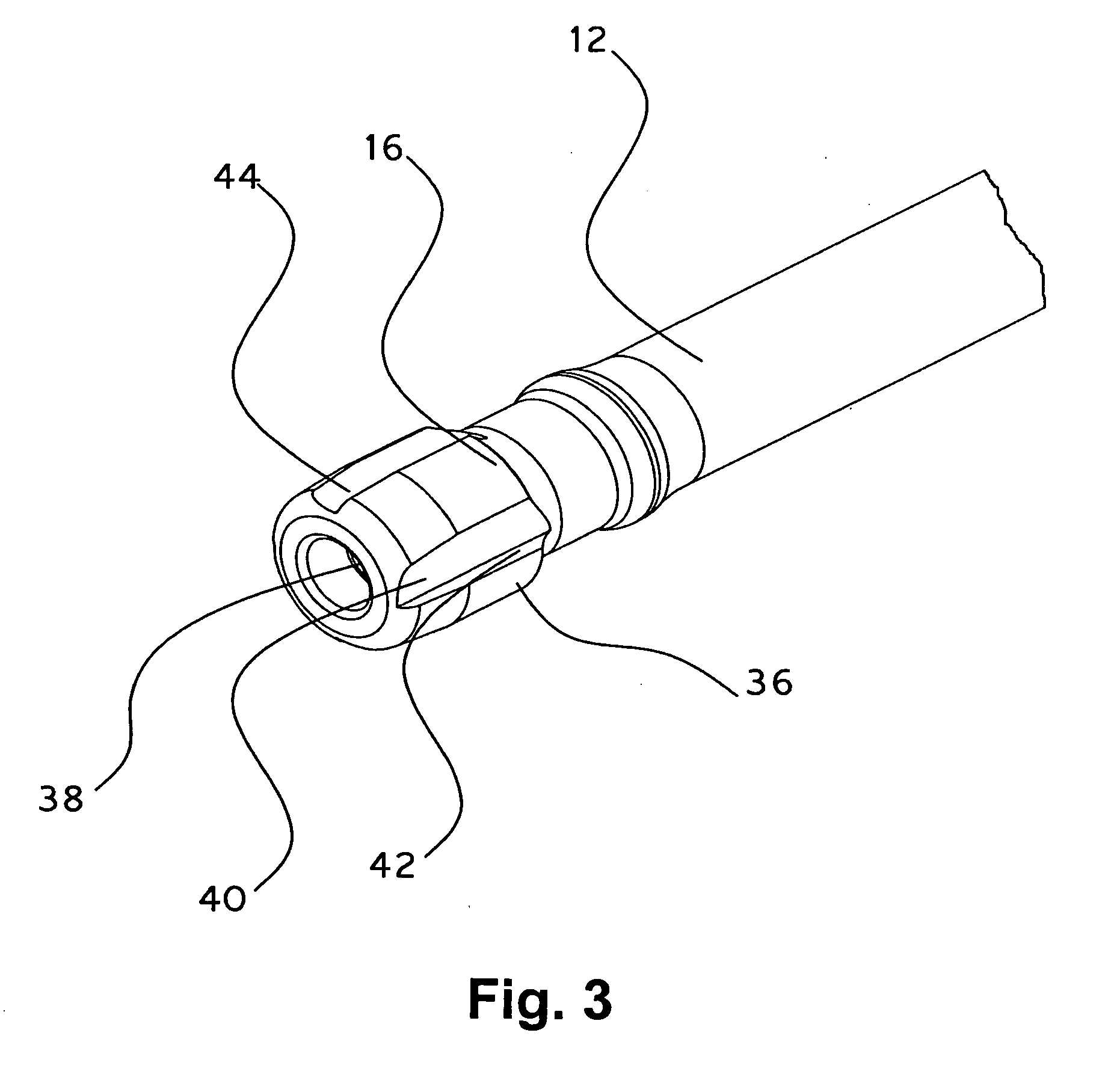
[0027]Referring now to the drawings, and particularly to FIG. 1 thereof, there is shown a longitudinal quarter section through a power transmission section 10 in accordance with an embodiment of the present invention. Power transmission section 10 as shown is part of a downhole drive line for drilling an oil or gas well, and it includes a drive shaft 12 having similarly configured ends including an input end 14 and an output end 16. Ends 14 and 16 of drive shaft 12 each include a centrally positioned ball recess that receives a respective pivot ball 18, 20. Axially opposite to ends 14 and 16 of drive shaft 12 are respective ball seats 22 and 24 that receive and contact an opposite ball surface region of respective pivot balls 18 and 20. Ball seats 22 and 24 are received in respective end adapters 26 and 28. End adapter 26 is at the power input end of power transmission section 10, and when it is part of a downhole drive arrangement it connects with an upstream drive connection to a ...


PUM


Abstract

A power transmission section particularly adapted for use in a downhole drilling system. A drive shaft is pivotally connected to input and output end connection members with pivot balls therebetween to allow pivoting of the shaft ends relative to the input and output end connection members. A plurality of ball segments having one spherically-curved surface are provided at each end of the drive shaft to engage with the input and output connection members and to transmit torque between the shaft ends and the input and output end connection members, regardless of the angular variation between the drive shaft longitudinal axis and the longitudinal axes of the input and output end connection members.

Description

BACKGROUND OF THE INVENTION[0001]1. Field of the Invention[0002]The present invention relates to a section of a rotatable drive line for transmitting torque between an input end and an output end. More particularly, the present invention relates to a power transmission line section in the form of an articulated drive shaft that can accept and transmit torque when the input and output ends of the line section are axially and angularly offset from each other.[0003]2. Description of the Related Art[0004]Power transmission sections in which the power input end of the transmission section is either intermittently or continuously axially or angularly offset from the power output end are utilized in numerous drive system applications. Examples of such applications include automotive drive trains and power transmission sections utilized in downhole drilling systems for drilling oil and gas wells.[0005]In that regard, in downhole drilling systems utilized in drilling applications, progressiv...

Claims


Application Information

Patent Timeline
Patent Type & Authority Applications(United States)
IPC IPC(8): F16D3/00
CPCE21B17/03F16D2300/06F16D3/20
Inventor WALL, KEVIN W.NICELY, JEREMY S.
Owner WALL KEVIN W
Why Eureka
Try Eureka