Automatic Choke System

a choke system and automatic technology, applied in the direction of machines/engines, mechanical equipment, electric control, etc., can solve the problems of insufficient in at least some aspects of automatic choke systems that do exist for application in the consumer market of small engines, complex and high cost of existing automatic choke systems, and undesirable engine performan

Inactive Publication Date: 2009-12-10
KOHLER CO
View PDF2 Cites 13 Cited by
  • Summary
  • Abstract
  • Description
  • Claims
  • Application Information

AI Technical Summary

Benefits of technology

[0008]Further, in at least some embodiments, the present invention relates to an automatic choke system for use in an internal combustion engine having a heat source and a choking mechanism including a choke plate. The choke system includes a first structure that is the thermally responsive, and a second structure connected at least indirectly at a first end to the first structure and at a second end to the choking mechanism. Additionally, the choke system also includes a heat transfer channel at least indirectly linking the heat source to the first structure. The heat transfer channel enables heated air to proceed from the heat source to the first structure and additionally allows for conduction of heat from the heat source to the first structure, whereby heat received at the first structure causes a response at the first structure, which in turn causes the second structure to operate so as to effect a movement of the choking mechanism.

Problems solved by technology

Although automatic choke systems are widely employed in the automotive industry, cable controlled choke systems are more common in the small engine industry, particularly small engines employed in consumer applications (e.g., engines for use in lawnmowers, snow throwers, snow blowers, etc.), due largely to the complexity and high cost of existing automatic choke systems.
Further, the automatic choke systems that do exist for application in the small engine consumer market are nevertheless inadequate in at least some respects.
For example, many conventional automatic choke systems for use in small engines are inadequately designed, such that during operation the systems can result in undesirable engine performance including, for example, generation of black smoke during start-up or during warm-up conditions, contamination of engine oil with fuel, and engine spark plug fouling.
Also, many conventional automatic choke systems for small engines do not account for variations in engine and carburetor design that necessitate varying degrees of choking during the restarting of an engine, after the engine has been running, during cool-down of the engine, and under other application load conditions.

Method used


Image

  • Automatic Choke System
  • Automatic Choke System
  • Automatic Choke System

Examples


Embodiment Construction

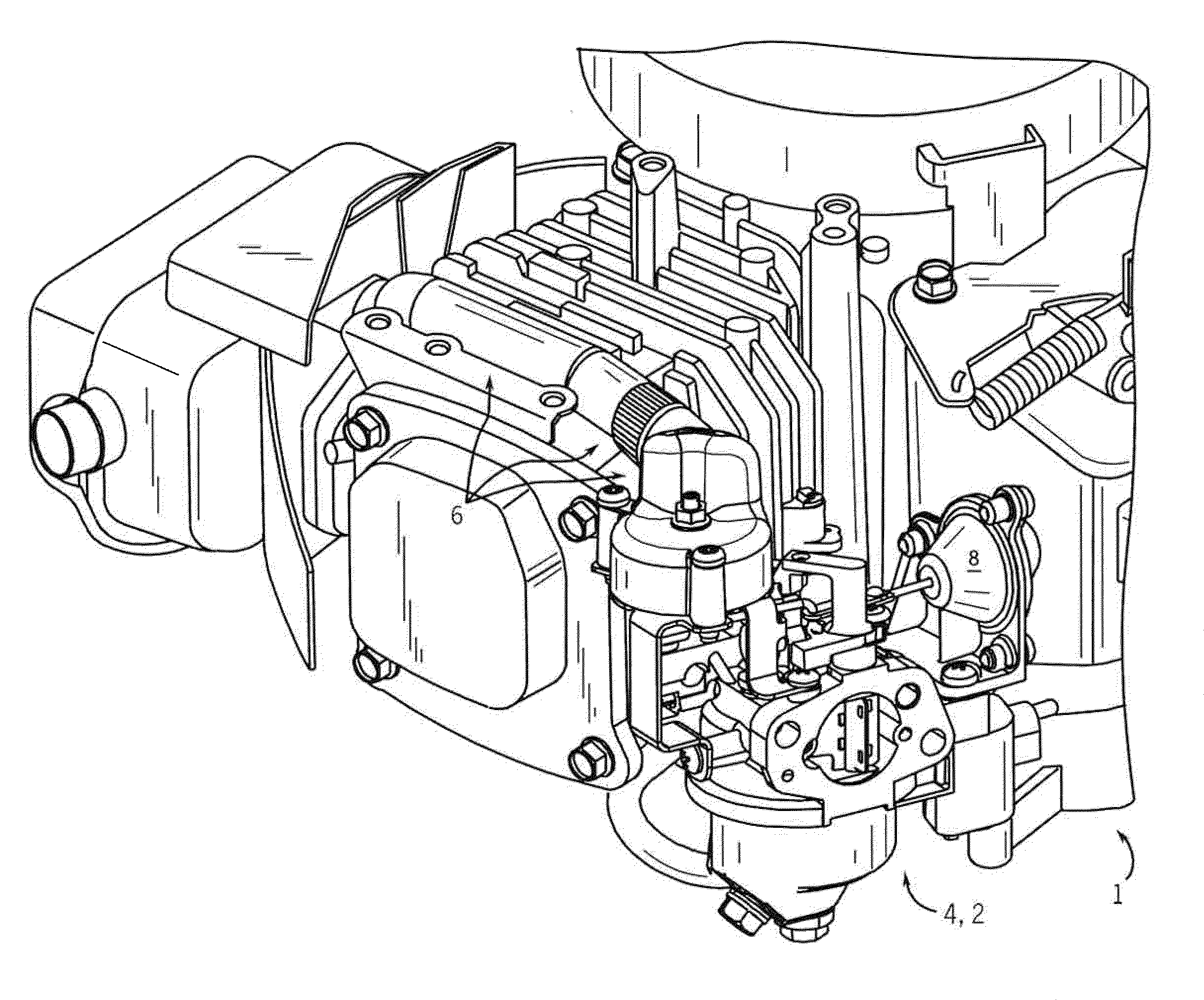
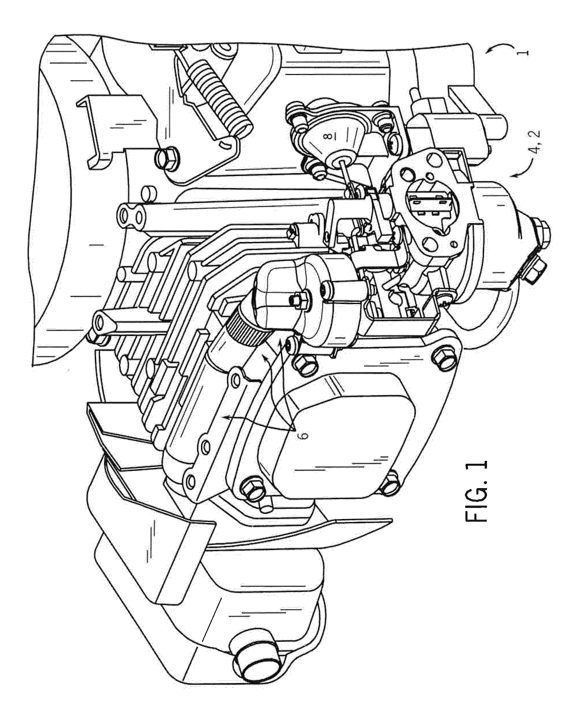
[0020]Referring first to FIG. 1, a perspective, cutaway view of an internal combustion engine 1 is shown in accordance with at least some embodiments of the present invention. As shown in FIG. 1, among other components, the internal combustion engine 1 includes a carburetor 2 on which is mounted an automatic choke system 4. The internal combustion engine 1 can be any of a wide variety of engines. Particularly, the automatic choke system 4 is contemplated for use in, as part of, or in conjunction or combination with a wide variety of engines (not shown) that can employ a carburetor such as the carburetor 2. In other embodiments, the automatic choke system 4 can be employed in other types of engines as well.

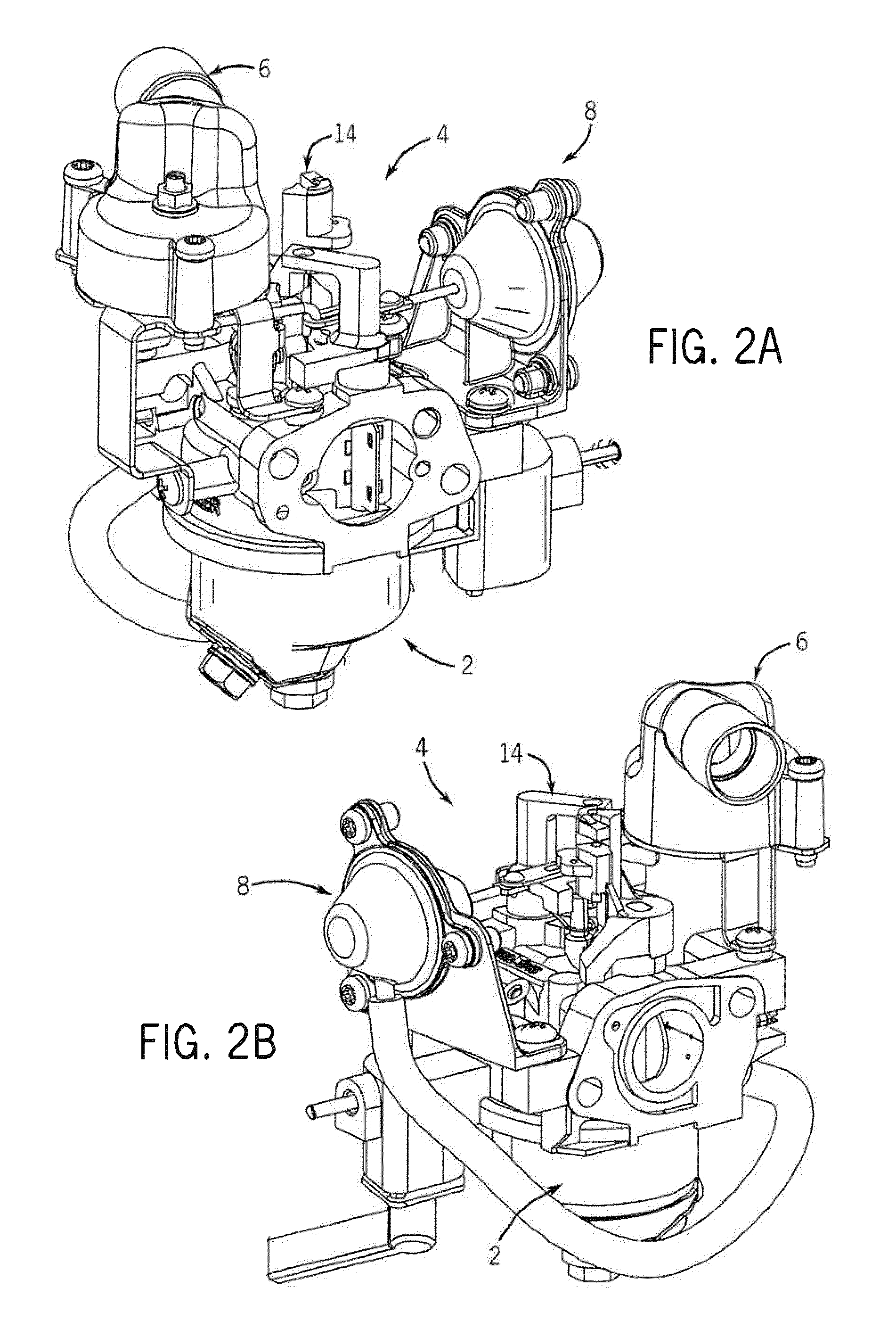
[0021]Further as shown in FIG. 1 (which shows the engine 1 with a cover removed), the automatic choke system 4 includes a thermal control system 6 and a vacuum control system 8, which are described in greater detail below. Specifically, the thermal and the vacuum control systems 6 ...


PUM


Abstract

In at least some embodiments, the present invention relates to an automatic choke system for use in an engine having a muffler and a choking mechanism that are located remotely apart from one another. The system includes a thermally responsive device, at least one component that serves to connect, at least in part, the device to the choking mechanism, and a further mechanism for conveying heat from the muffler to the device. Additionally, the system in at least one embodiment includes at least one of: (a) a pipe for conveying a fluid from a first location proximate the muffler to a second location proximate the device, the pipe being comprised within the further mechanism; and (b) a rotatable axle that spans a majority of a distance between the first location and a third location that is proximate the choking mechanism, the axle being comprised within the at least one component.

Description

CROSS-REFERENCE TO RELATED APPLICATIONS[0001]This application claims the benefit of U.S. provisional patent application No. 61 / 059,239 entitled “Automatic Choke System” filed on Jun. 5, 2008, which is hereby incorporated by reference herein.FIELD OF THE INVENTION[0002]The present invention relates to internal combustion engines and, more particularly, to choke systems employed in internal combustion engines.BACKGROUND OF THE INVENTION[0003]Engine start and run quality at various temperatures is typically dependent on fuel enrichment. A proper variation of fuel enrichment for a naturally aspirated gasoline engine can be achieved by way of a carburetor and a choke plate used in conjunction with one another. Generally speaking, the choke plate is capable of operating to constrict the flow of air into the carburetor inlet, such that the air passing through the constricted inlet passes through a smaller opening resulting in an increased velocity and decreased pressure within the body (ve...

Claims


Application Information

Patent Timeline
Patent Type & Authority Applications(United States)
IPC IPC(8): F01N5/02F02M1/00F02D9/00
CPCF02M1/10
Inventor SOTIRIADES, ALEKO D.
Owner KOHLER CO
Why Eureka
Try Eureka