
Capacitive sensor assembly for determining relative position

a capacitance sensor and relative position technology, applied in the field of capacitance sensors, can solve the problems of inability to reliably measure the level of liquids in other directions, mechanical and/or electrical breakdown, and inability to reliably measure the level of liquids, etc., to achieve the effect of replacement, and reducing the cost of maintenan

Inactive Publication Date: 2009-12-10
ROCHESTER GAUGES INC
View PDF54 Cites 63 Cited by
  • Summary
  • Abstract
  • Description
  • Claims
  • Application Information

AI Technical Summary

Problems solved by technology

Such sensors are prone to wear, mechanical and / or electrical breakdown or inaccurate liquid level detection.
Although variable capacitance probes have been developed to overcome these drawbacks, they are cost-prohibitive in many applications and are typically limited to measuring a certain type of liquid, since different liquids will have different dielectric properties.
In addition, a variable capacitance probe designed to measure fuel level normally cannot be used for measuring water level due to the different dielectric properties associated with different liquids.
Since capacitance is directly dependent on the dielectric constant, a transducer designed for measuring the level of one type of liquid could not be relied upon for measuring other types of liquids.
However, even when the transducer is designed for measuring only one type of liquid, such as gasoline, the dielectric constant can change due to different gasoline formulations, the presence of water, alcohol, detergents, additives, as well as environmental factors such as temperature, pressure and humidity, thus leading to significant measurement inaccuracies.
For example, the reference capacitor may be exposed to water or other contaminants at the bottom of a fuel tank which may lead to inaccurate dielectric compensation.
In such circumstances, prior art fuel sensors are usually inadequate to accommodate these shapes while accurately measuring fuel level.
In other circumstances, it may be difficult or impractical to penetrate the tank with a liquid level sensor.
In addition, the electronics associated with capacitive measurement and compensation are relatively expensive and are thus priced out of markets where there is a long-felt need for low-cost yet highly accurate liquid level transducers and other sensors for measuring relative position and / or movement between objects.

Method used


Image

  • Capacitive sensor assembly for determining relative position
  • Capacitive sensor assembly for determining relative position
  • Capacitive sensor assembly for determining relative position

Examples


Embodiment Construction

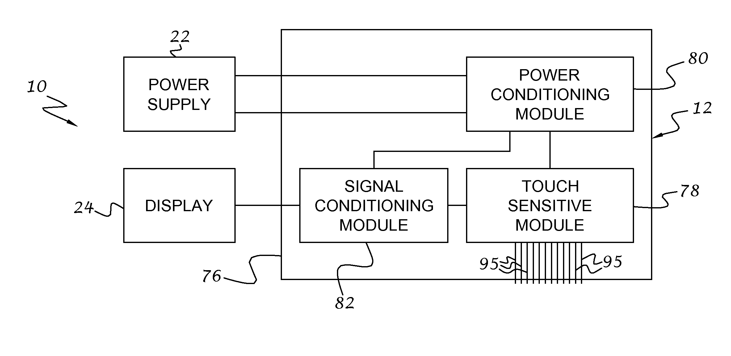
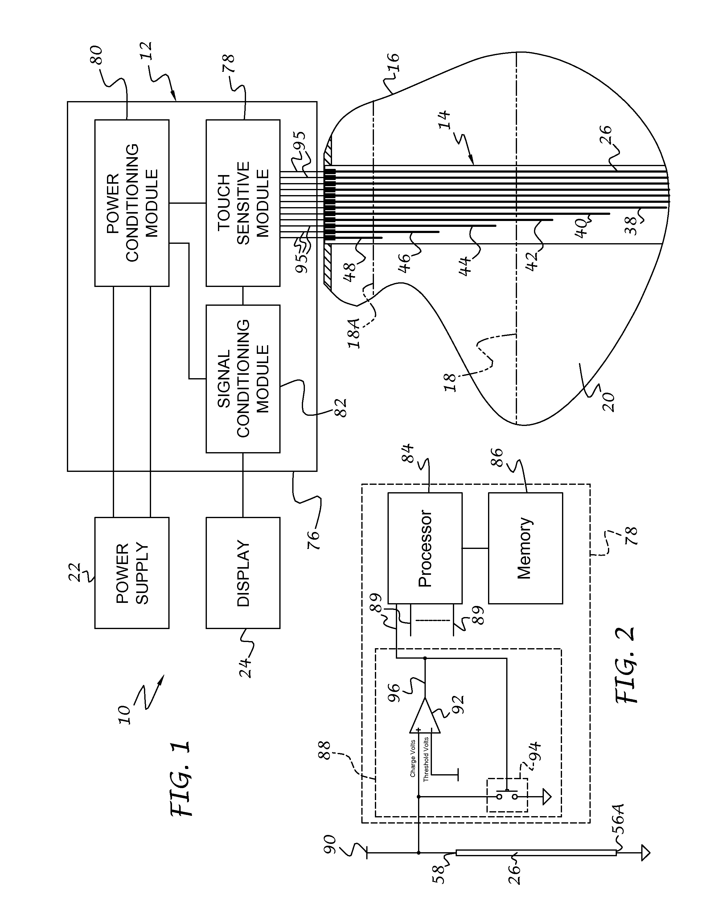
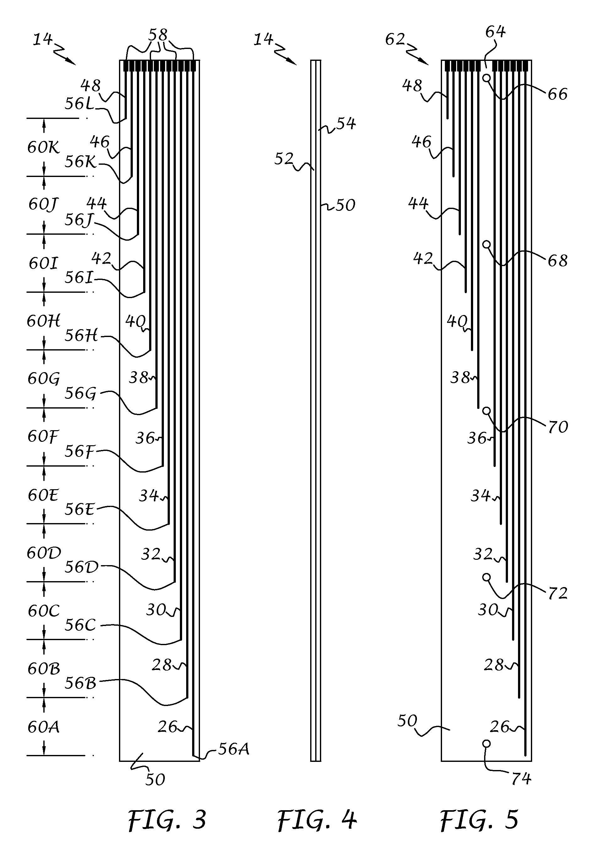
[0033]Referring to the drawings, and to FIG. 1 in particular, a capacitive transducer 10 in accordance with an exemplary embodiment of the present invention is illustrated. The capacitive transducer 10 preferably includes an electronics section 12 and a probe section 14 that electrically interfaces with the electronics section. The probe section 14 is adapted for mounting inside or outside a tank 16, vessel or other container for measuring a level, as denoted by numerals 18 and 18A, of a fluent material 20 within the container. The electronics section 12 is preferably powered by an external power supply 22 and sends appropriate signals to an external display 24 or other interface, such as control circuitry (not shown) for controlling inflow and outflow of material, upon determination of material level within the container. The fluent material 20 to be measured can be in the form of liquid or granular materials. Practical applications of this invention include, but are not limited to...


PUM


Abstract

A capacitive sensor assembly for detecting relative movement or position between objects, such as liquid level in a tank or reservoir, movement of one machine component with respect to another, and so on, includes one or more antenna probes connected to an integrated chip normally associated with touch-screen displays. Each antenna probe operates independently and may be formed as insulated conductive wires or conductive traces between layers of a stiff or flexible substrate, such as a PCB, with the substrate material serving as the insulating layers. Each antenna probe has a different length representing different measurement positions or locations between the objects being measured to provide dynamic calibration of the measurement under changing environmental conditions.

Description

CROSS REFERENCE TO RELATED APPLICATIONS[0001]This application is related to U.S. application Ser. No. ______ and U.S. application Ser. No. ______ filed on even date herewith, the disclosures of which are hereby incorporated by reference.BACKGROUND OF THE INVENTION[0002]This invention relates to capacitive sensors, and more particularly to variable capacitance sensors for determining relative position or movement between objects, such as movement of liquid within a tank, movement of one machine component with respect to another machine component, as well as other measurable parameters.[0003]Transducers for measuring liquid level, linear or angular position and movement, pressure, torque, and the like, are often used in vehicles, industrial equipment and other systems and components. The electrical output of such transducers changes in response to a change in the component being measured. The electrical output is typically in the form of a change in resistance, capacitance, current fl...

Claims


Application Information

Patent Timeline
IPC IPC(8): G01F23/26G01R27/26
CPCG01F23/265G01F25/0061G01F23/268G01F25/20
Inventor ROSS, JR., HERBERT G.TAYLOR, CARL ALAN
Owner ROCHESTER GAUGES INC
Features
  • Generate Ideas
  • Intellectual Property
  • Life Sciences
  • Materials
  • Tech Scout
  • Unparalleled Data Quality
  • Higher Quality Content
  • 60% Fewer Hallucinations
Learn More