Torque limiting mechanism

a technology of torque limitation and torque, applied in the direction of slip couplings, couplings, couplings, etc., can solve the problems of output torque having a magnitude exceeding the prescribed value and falling at a higher frictional torque, and the output torque may be transmitted to the output shaft undesirably, so as to reduce friction between friction plates and reduce frictional torque

Active Publication Date: 2009-12-10
SHIMADZU CORP
View PDF6 Cites 19 Cited by
  • Summary
  • Abstract
  • Description
  • Claims
  • Application Information

AI Technical Summary

Benefits of technology

[0008]According to the present invention, a ball ramp section is attached to a torque limiting mechanism having a slip clutch section intervening between an input shaft and an output shaft for reducing friction between friction plates forming the slip clutch section by transmitting an input torque at least partially to one cam element of the ball ramp section and utilizing an axial thrust produced at the ball ramp section in accordance with a magnitude of the torque thus transmitted. In general, friction plates forming a slip clutch are elastically biased so as to be pressed against each other. When an excessive torque having a magnitude exceeding a prescribed value works, the torque limiting mechanism reduces the frictional torque produced by the friction plates by causing the ball ramp section to produce an axial thrust of a required magnitude and balancing the axial thrust against the elastically biasing force.
[0010]According to the present invention, it is possible to realize a high-precision torque limiting mechanism capable of limiting the output torque to a magnitude of not more than the prescribed value, as well as to reduce the frictional torque produced upon occurrence of the slip.

Problems solved by technology

For this reason, even when the ball ramp section is caused to start operating at the time an input torque of the prescribed value works, namely, even when the ball ramp section produces an axial thrust to cause the two cam elements to move away from each other at that time, it is possible that the decrease in frictional torque fails to catch up a further increase in input torque, resulting in occurrence of a slip at a higher frictional torque than estimated.
Stated otherwise, an output torque having a magnitude exceeding the prescribed value may be transmitted to the output shaft undesirably.

Method used


Image

  • Torque limiting mechanism
  • Torque limiting mechanism
  • Torque limiting mechanism

Examples


Embodiment Construction

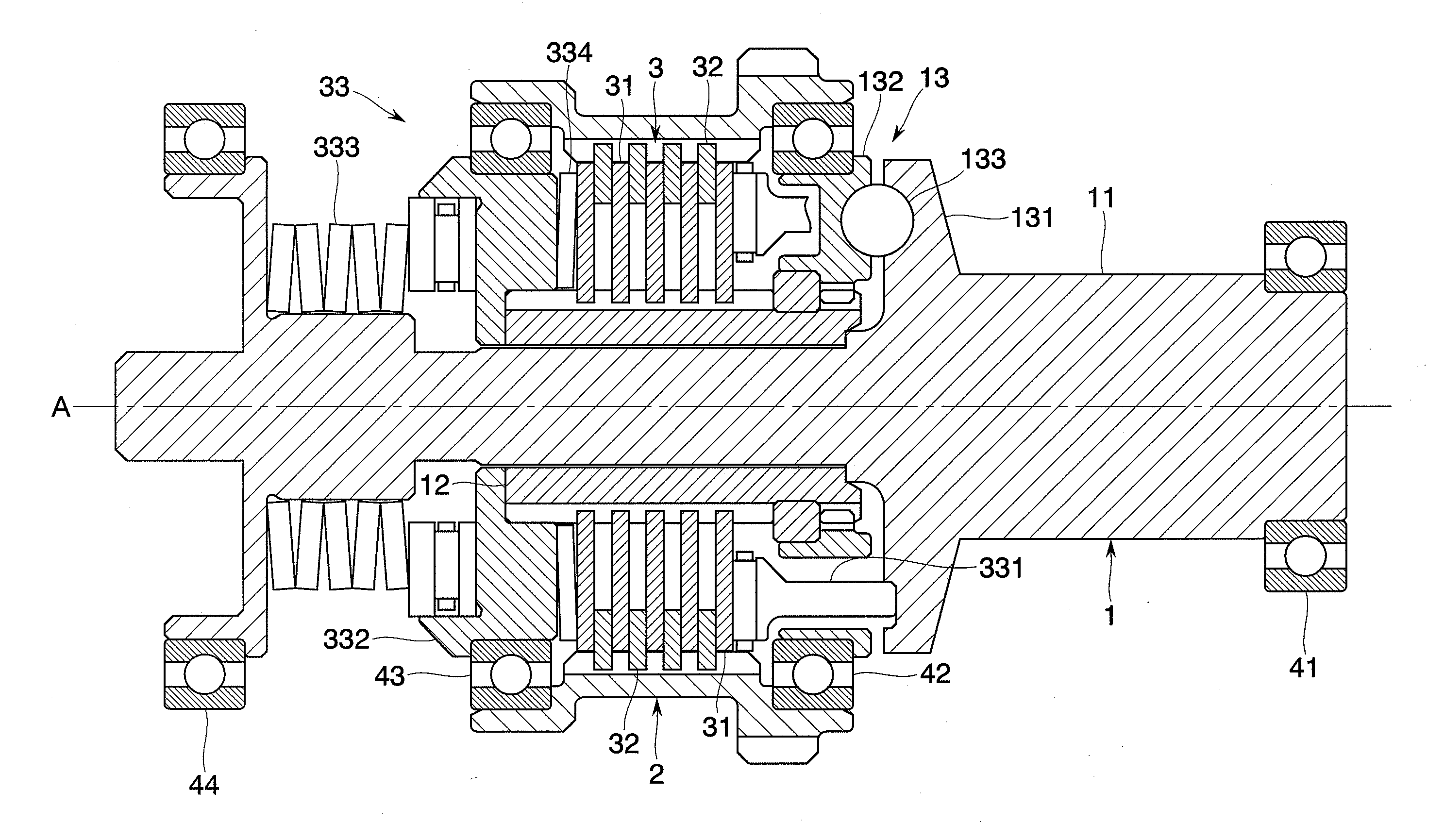
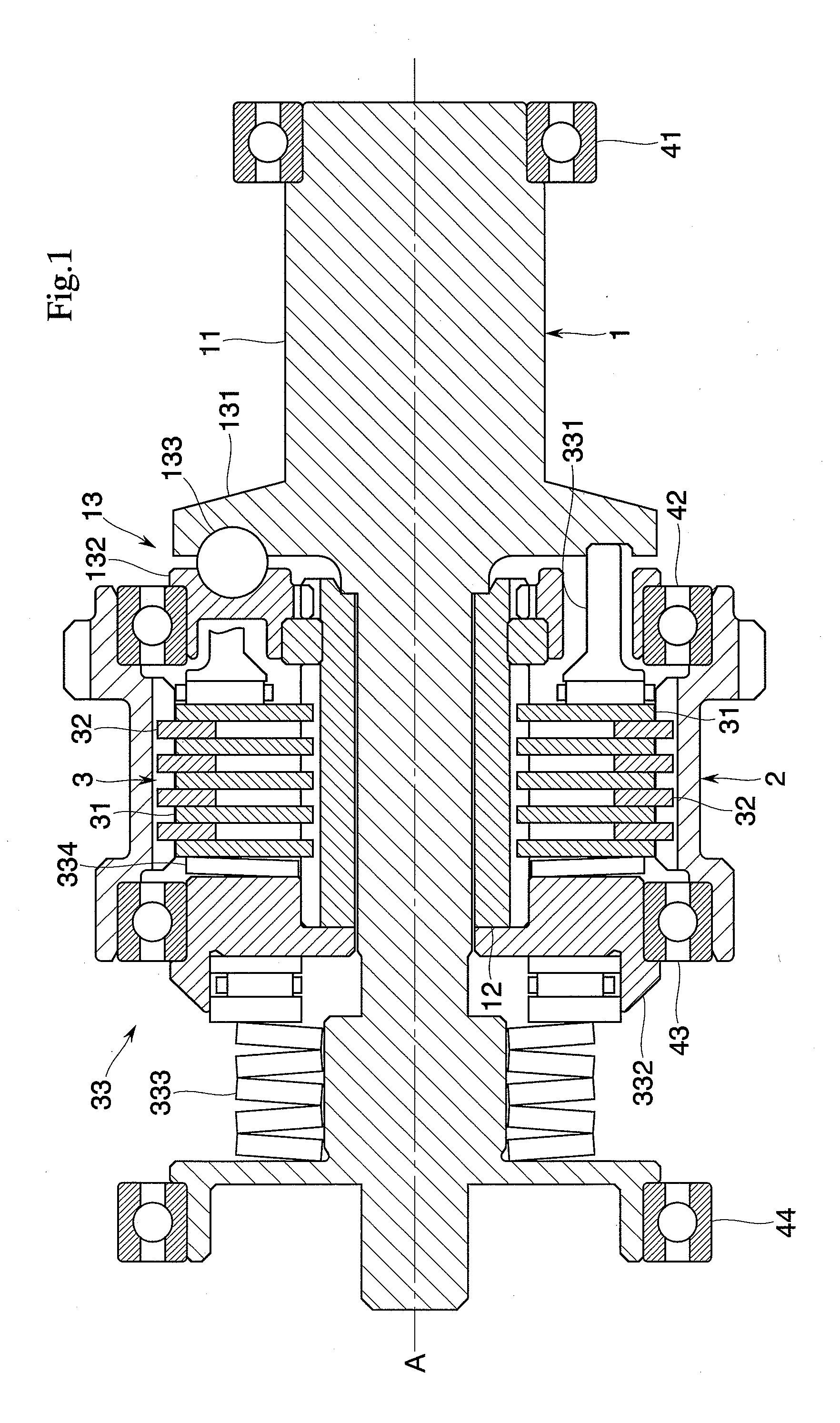
[0015]Hereinafter, one embodiment of the present invention will be described with reference to the drawings. As shown in FIG. 1, a torque limiting mechanism according to the present embodiment includes an input shaft (or output shaft) 1 and an output shaft (or input shaft) 2 which are driven to rotate about the same axis A, and a slip clutch section 3 intervening between the input shaft 1 and the output shaft 2 to interconnect the two shafts for transmitting a torque inputted to the input shaft 1 to the output shaft 2.

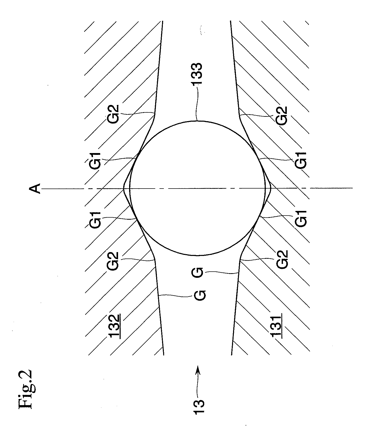
[0016]The input shaft 1 includes an input shaft body 11, an input-side rotor member 12 driven by the input shaft body 11, and a ball ramp section 13 intervening between the input shaft body 11 and the rotor member 12. The rotor member 12 is displaceable along the axis A independently to the input shaft body 11 and rotatable about the axis A. The ball ramp section 13 includes cam elements 131 and 132 forming a pair along the axis A, and a ball 133 held between recesses ...


PUM


Abstract

An intended object of the present invention is to realize a high-precision torque limiting mechanism capable of limiting an output torque to a magnitude of not more than a prescribed value, as well as to reduce a frictional torque produced upon occurrence of a slip. To accomplish this object, a ball ramp section 13 is attached to a slip clutch section 3 for reducing friction between friction plates 31 and 32 forming the slip clutch section 3 and limiting a torque to be transmitted by utilizing an axial thrust produced at the ball ramp section 13 in accordance with the magnitude of an input torque. The precision with which the torque to be transmitted is limited is enhanced by making improvements to the shape of an internal side surface of a recess G formed in each of cam elements 131 and 132 of the ball ramp section 13.

Description

TECHNICAL FIELD[0001]The present invention relates to power transmission systems of aircrafts, general industrial machines and the like and, more particularly, to a torque limiting mechanism for limiting transmission of an excessive input torque when such an excessive input torque works.BACKGROUND ART[0002]A slip clutch is well-known as a mechanism capable of transmitting a torque from an input shaft to an output shaft while limiting transmission of an excessive input torque when such an excessive input torque works (see patent documents noted below for example). The slip clutch is configured to transmit a torque through friction between a friction plate spline-coupled to the input shaft and a friction plate spline-coupled to the output shaft and limit transmission of the torque by causing the friction plates to slip relative to each other when an excessive input torque works.[0003]Presently, however, a problem exists that it is difficult to reliably limit an output torque to a desi...

Claims


Application Information

Patent Timeline
Patent Type & Authority Applications(United States)
IPC IPC(8): F16D43/206
CPCF16D7/027F16D2023/123F16D43/216
Inventor MURAKAMI, HIROAKI
Owner SHIMADZU CORP
Why Eureka
Try Eureka