Apparatus and Method for Vaporizing Volatile Material

a technology of volatile materials and apparatus, which is applied in the direction of manufacturing tools, tobacco, other medical devices, etc., can solve the problems of needing to send the device away, increasing the likelihood of inadvertent burning of substances by contact with heating elements, and damage to circuit boards

Inactive Publication Date: 2009-12-10
SELENSKI TIM +1
View PDF6 Cites 90 Cited by
  • Summary
  • Abstract
  • Description
  • Claims
  • Application Information

AI Technical Summary

Problems solved by technology

One problem that may arise is that close proximity spacing between the current controlling circuit board the heating element fixed thereto for control thereby may result in damage to the circuit board resulting from discharged heat.
Typically, electrical connection between the heating element and the controls is hard-wired, often resulting in a need to send in the device away for repair or replace the entire device should one of these two components fail or need replacement.
Attempts to produce a compact vaporization unit, at least one commercially available product has been produced with an exposed heating element that may have detrimental effects on safety and may require extremely close proximity to the substance to be vaporized to achieve sufficient heating thereof when used to attempt vaporization in the bowl of an existing smoking device, which may increase the likelihood of inadvertently burning the substance by contact with the heating element.
Another commercially available handheld unit is not intended for use with existing smoking devices, but requires partial disassembly to refill the unit and may be quite limited in the amount of substance it can contain, perhaps leading to a need for multiple refills to release a desirable amount of volatile material.
Other portable units have been produced that rely on a separate flame source for heating of the substance indirectly through a glass body and thus may also increase the risk of burning rather than vaporizing.

Method used


Image

  • Apparatus and Method for Vaporizing Volatile Material
  • Apparatus and Method for Vaporizing Volatile Material
  • Apparatus and Method for Vaporizing Volatile Material

Examples


first embodiment

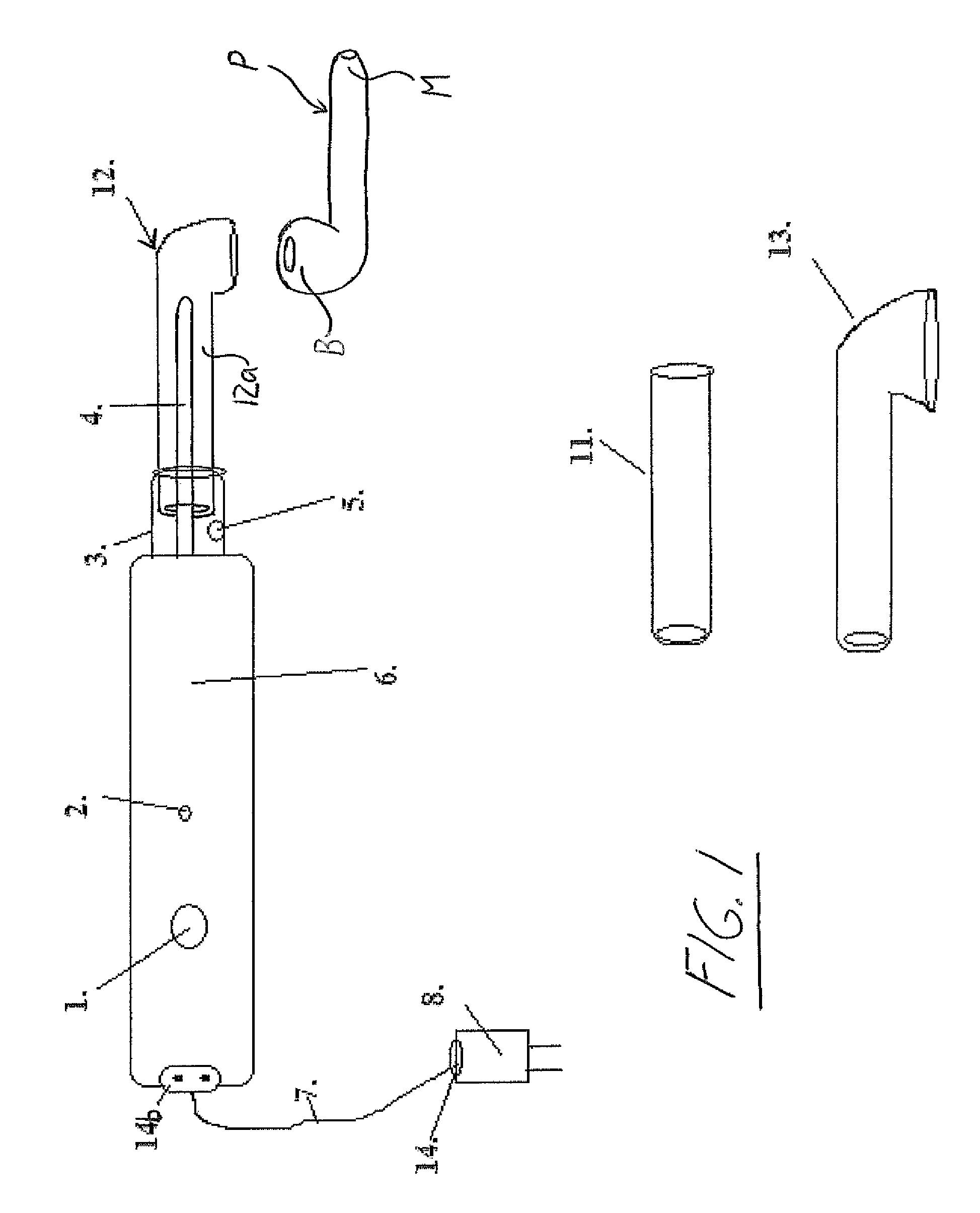
[0057]FIG. 1 shows an exterior of a first embodiment vaporizer lighter having a handle body 6 which may be made of any of a variety of suitable materials including high performance plastic composite resins, ceramics, titanium or other metals, wood, glass or any combination thereof. The handle body 6 houses a temperature control unit with power on / off ability and temperature control provided by one or more pushbutton, rotational knob or other type of switch 1 operable at the exterior of the handle body 6. A power cord 7 provides electrical wiring which may be releasable from one or both of the handle body 6 and a power source plug 8 by way of an optional cord detaching connector 14. The plug end 8 may be of a type engagable with a conventional North American 110V household outlet, but is not restricted to any particular voltage source. For example, the plug may be of various types suitable for household outlets which vary globally in plug and socket shapes and configurations and volt...

second embodiment

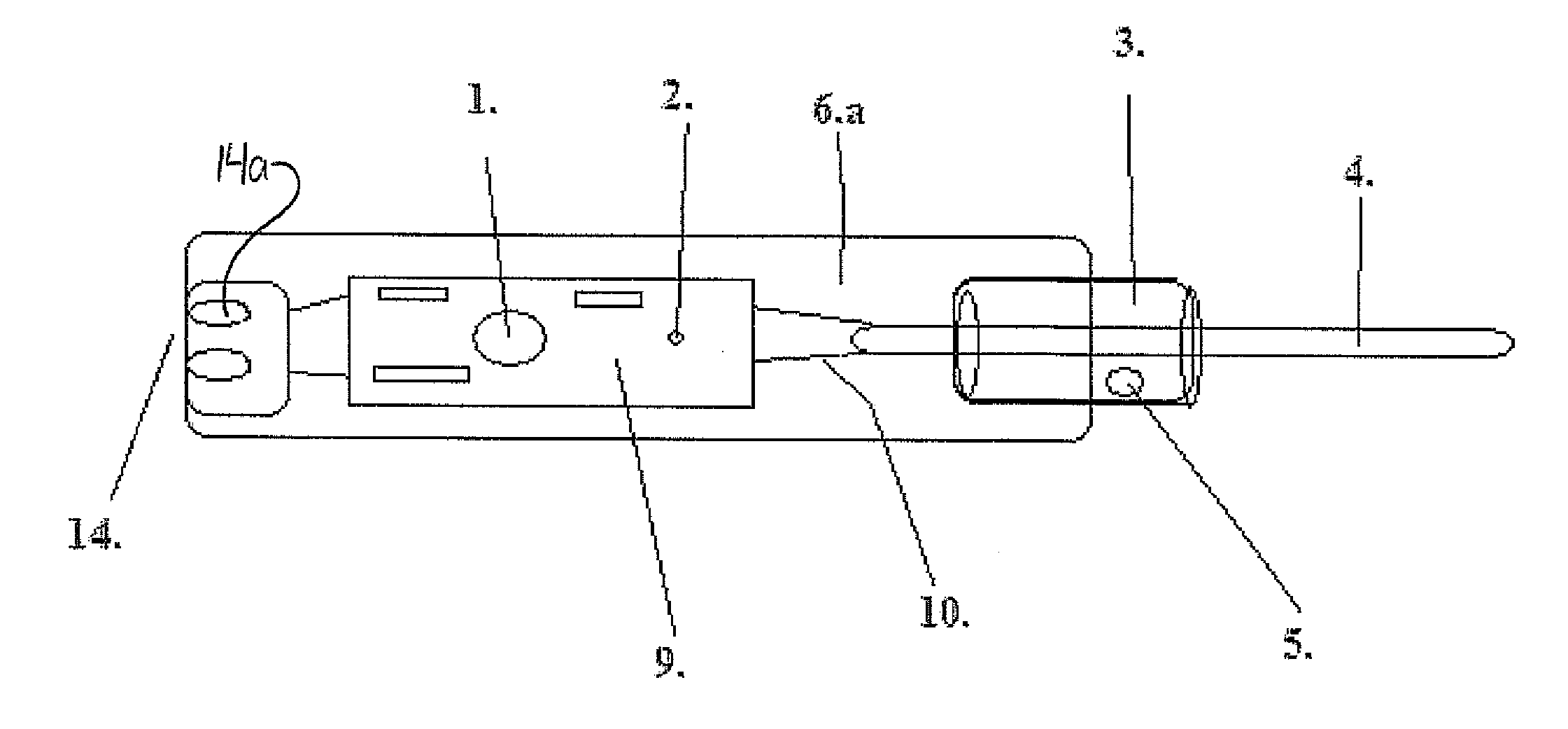
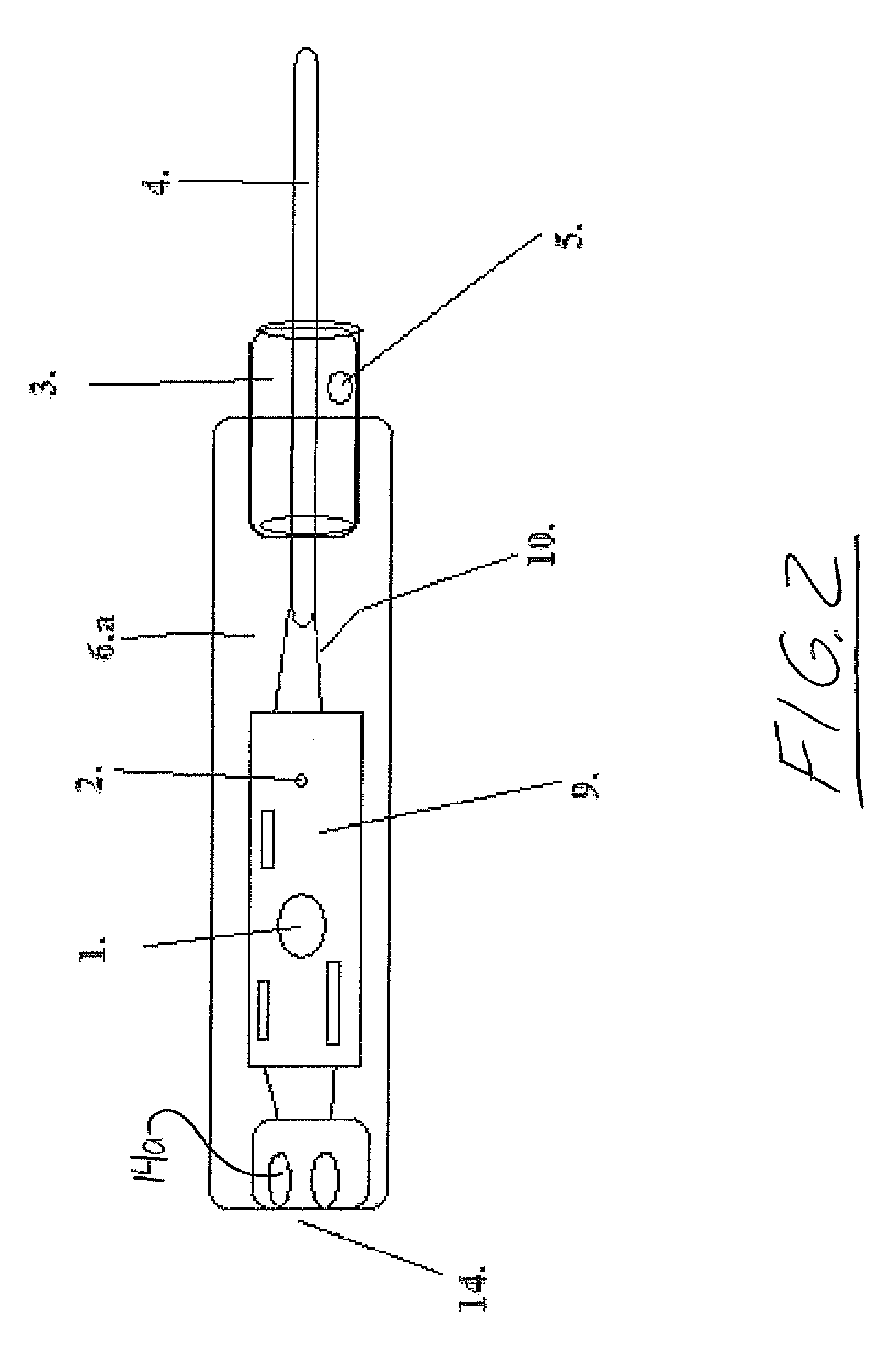
[0067]The additional flexible cord 7a allows free relative movement between the separate control module and heating module housings within a limited volume of space. The housing of the control unit and the heating element 4 within two physically separate housings prevents damage to the control unit that may otherwise result from heating or malfunction of the heating element 4. The detachable connection between the two modules facilitates replacement of an old or defective heating element 4 by replacing the entire heating module, thereby eliminating the need to open or dismantle components to replace just the heating element 4 so that repair of the vaporizer lighter can be effected by the owner or user by simply purchasing a replacement heating module (consisting of handle body 6, heating element 4, electrical connection component 14a, and adapter body 3 for the illustrated second embodiment vaporizer / lighter) and plugging it onto the end of flexible cord 7a. This avoids the need to ...

third embodiment

[0074]Alternatively, the third embodiment vaporizer may be used without the hose attachment to simply release vaporized material into the surrounding environment. In such operation, the substance used may be inserted into the heating chamber directly or by placement into a hose-free material holder for subsequent insertion into the heating chamber 18. For example, the vaporizer may use an aromatherapy essential oil insert, for example a porous pad having had drops of an essential oil applied thereto from a commercially available supply jar or vial, to release a scent into the vehicle interior.

[0075]It will be appreciated that although not shown, the third embodiment vaporizer may be equipped with one or both of an on / off control to allow the vaporizer to remain in the lighter socket even when not in use and a temperature control to facilitate control over the level to which the element is heated. On the other hand, the vaporizer may be produced as a simple plug in unit designed to a...


PUM

PropertyMeasurementUnit
voltageaaaaaaaaaa
volatileaaaaaaaaaa
electricalaaaaaaaaaa

Abstract

A volatile material vaporizing apparatus features a heating element and heating element controls supported in separate housings to avoid exposure of the controls to heat produced by the heating element. Another embodiment features an elongate heating element supported entirely within a housing having an open end sized to fit over the bowl of an existing smoking device so that drawing air through the smoking device induces airflow into an inlet opening of the housing, along the heating element disposed therein, and onward to the smoking device. In another embodiment, a housing includes a plug portion slidable into a cigarette lighter socket of a vehicle to establish connection with electrical contacts therein. A heating chamber opposite the plug portion is in fluid communication with a heating element in the housing, and an inlet opening allows airflow into the housing for flow along the heating element into the heating chamber.

Description

[0001]This application claims benefit under 35 U.S.C. 119 of U.S. Provisional Patent Application Ser. No. 61 / 058,960, filed Jun. 5, 2008.[0002]The present invention relates generally to inhalation of volatile materials vaporized and released from natural substances, and more particularly to vaporization of volatile materials for inhalation without combustion.BACKGROUND OF THE INVENTION[0003]Within the art, it is known to use the process of vaporization of volatile materials contained within natural substances to enable inhalation of these materials without combustion to attempt to reduce detrimental health effects associated with conventional combustion-initiated smoking practices typically used to extract ingredients from substances such as medical cannabis, tobacco or other herbal products or smoking materials.[0004]Several devices have been developed with this purpose in mind. Some such vaporization devices use an electrically operated heating element to heat air to a temperature...

Claims


Application Information

Patent Timeline
Patent Type & Authority Applications(United States)
IPC IPC(8): H05B3/00A24F40/20A24F40/46A24F40/485A24F40/50
CPCA24F47/008A61M11/041A61M15/0021A61M2205/8262A61M11/042A61M15/06A61M11/048A24F40/46A24F40/50A24F40/485A24F40/20
Inventor SELENSKI, TIMCOOK, JASON
Owner SELENSKI TIM
Why Eureka
Try Eureka