Hydraulic unit support structure

a technology of supporting structure and hydraulic unit, which is applied in the direction of machine supporting, braking system, other domestic objects, etc., can solve the problems of impaired shock absorption function, and achieve the effect of good shock absorption function and excellent assembly eas

Active Publication Date: 2009-12-10
TOYOTA JIDOSHA KK +1
View PDF17 Cites 9 Cited by
  • Summary
  • Abstract
  • Description
  • Claims
  • Application Information

AI Technical Summary

Benefits of technology

[0006]The invention provides a hydraulic unit support structure that enables a shock-absorbing member to exhibit a good shock absorbing function, while maintaining excellent ease of assembly.

Problems solved by technology

However, this arrangement may raise a problem in that, although the ease of assembly is increased, the shock absorbing function may be impaired due to the reduction in an area in which the shock-absorbing member makes contact with seat surfaces of the bracket around the slot.

Method used


Image

  • Hydraulic unit support structure
  • Hydraulic unit support structure
  • Hydraulic unit support structure

Examples


Embodiment Construction

[0025]Various embodiments of the present invention will now be described in detail with reference to the accompanying drawings.

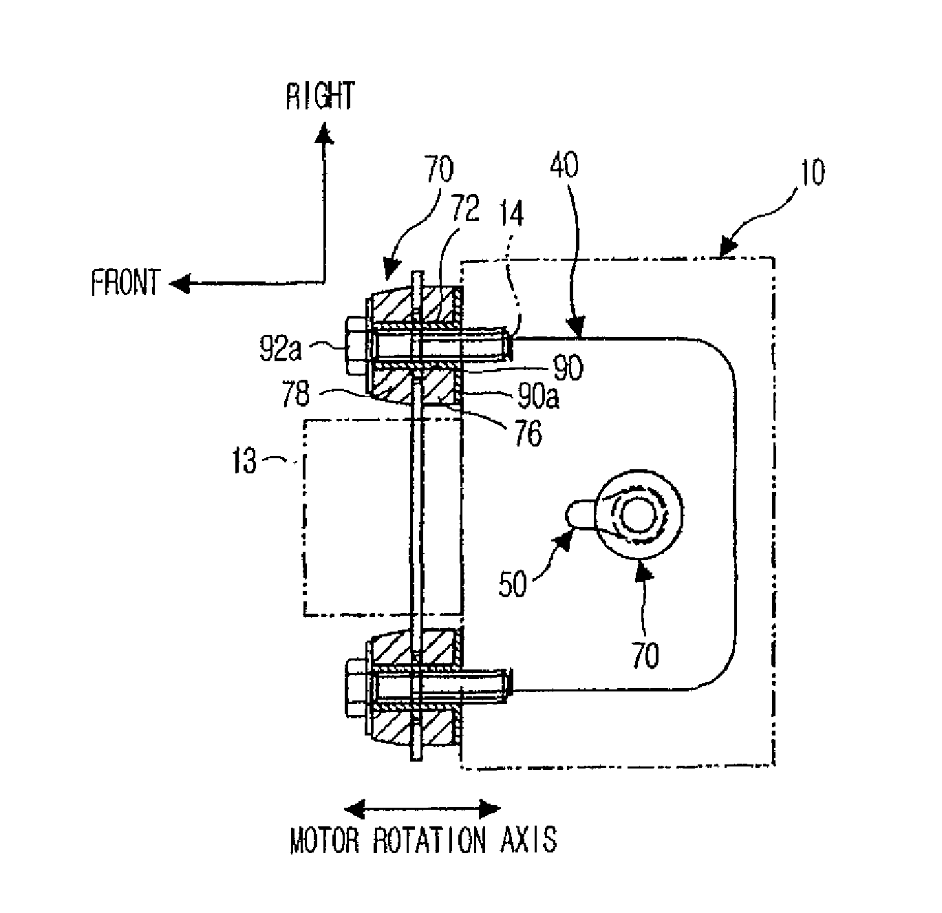
[0026]FIG. 1 is a perspective view showing a hydraulic unit 10 supported by a hydraulic unit support structure according to an embodiment of the present invention. The hydraulic unit 10 shown in FIG. 1 forms a part of a brake actuator. A motor or pump for generating a high brake pressure and various electromagnetic valves are received within the hydraulic unit 10. Furthermore, a skid control computer that governs the braking control for an ABS (Anti-lock Brake System), a brake assist, or the like may be incorporated in the hydraulic unit 10. Typically, the hydraulic unit 10 is mounted within an engine compartment. In the following description, directions (top, bottom, left, right, front and rear directions) will be defined as represented in FIG. 1 under the condition that the hydraulic unit 10 is mounted in a typical mounting condition.

[0027]A plurality of c...


PUM


Abstract

A hydraulic unit support structure includes a bracket (40) having a slot (50) and seat surfaces formed around the slot, and a shock-absorbing member (70) attached to the hydraulic unit (10). The shock-absorbing member (70) is fitted into the slot (50) of the bracket so that the hydraulic unit is supported on the bracket by the shock-absorbing member. The shock-absorbing member has a small-diameter portion (74) inserted into the slot of the bracket and large-diameter portions (76, 78) making contact with the seat surfaces of the bracket around the slot. The slot of the bracket has an insertion-fit region (52) formed at one end of the slot in the long-axis direction and a reduced width region formed at a position spaced apart from the one end in the long-axis direction by a distance substantially equal to the diameter of the small-diameter portion.

Description

BACKGROUND OF THE INVENTION[0001]1. Field of the Invention[0002]The present invention relates to a hydraulic unit support structure that supports a hydraulic unit on a bracket through a shock-absorbing member attached to the hydraulic unit by fitting the shock-absorbing member into a slot formed in the bracket.[0003]2. Description of Related Art[0004]Regarding the hydraulic unit support structure, there is conventionally known an arrangement in which a shock-absorbing member is fitted into a slot-like opening of an oval or elliptical shape formed in a bracket (see, e.g., Japanese International Application Publication No. 2004-521276).[0005]In the meantime, with this kind of hydraulic unit support structure, a relatively large clearance is left between the shock-absorbing member and the slot, to facilitate fitting the shock-absorbing member into the slot during assembly. However, this arrangement may raise a problem in that, although the ease of assembly is increased, the shock absor...

Claims


Application Information

Patent Timeline
Patent Type & Authority Applications(United States)
IPC IPC(8): F16M13/02
CPCF16F1/3732B60T8/3685
Inventor TETSUDA, TOSHIYUKIKODAN, MASASHIFURUHATA, KATSUYUKI
Owner TOYOTA JIDOSHA KK
Why Eureka
Try Eureka