Ortho-Mode Transducer

a transducer and orthomode technology, applied in the field of waveguide devices, can solve the problems of hammering the sealing of the complete unit for the usual outdoor application, and achieve the effect of compact size, high performance properties, and compact device siz

Inactive Publication Date: 2009-12-10
TELEFON AB LM ERICSSON (PUBL)
View PDF9 Cites 10 Cited by
  • Summary
  • Abstract
  • Description
  • Claims
  • Application Information

AI Technical Summary

Benefits of technology

[0006]Accordingly, the invention seeks to preferably mitigate, alleviate or eliminate one or more of the disadvantages mentioned above singly or in any combination.
[0009]The present invention beneficially allows for the interfaces for the orthogonal polarisations to be realised in one plane without any parting plane of the unit through the flange connections with preserving high performance properties and compact size of the device. The compact size, in turn, facilitates manufacturing. Sealing of the complete unit is easily performed by a single closed O-ring between the two milled parts, which is very advantageous for outdoor application of antenna-feed systems.

Problems solved by technology

3.8.12c and 3.8.13c in the above reference) that provide the interface ports in a same plane, but they are of a secondary importance due to their poor performance properties.
The drawback of the latter solution is that the parting plane is through the interconnecting flanges which hamper the necessary sealing of the complete unit for the usual outdoor applications.

Method used


Image

  • Ortho-Mode Transducer
  • Ortho-Mode Transducer
  • Ortho-Mode Transducer

Examples


Embodiment Construction

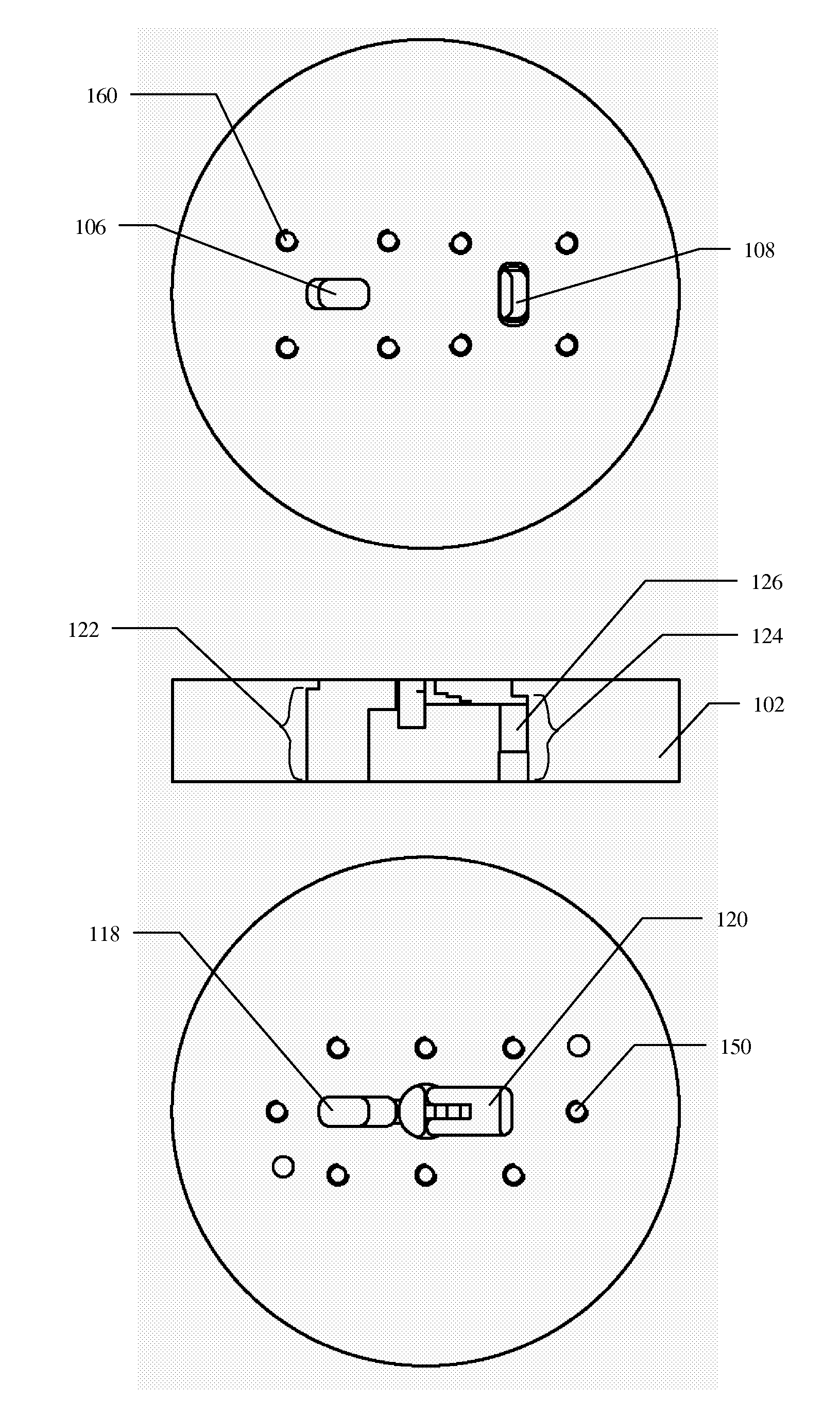
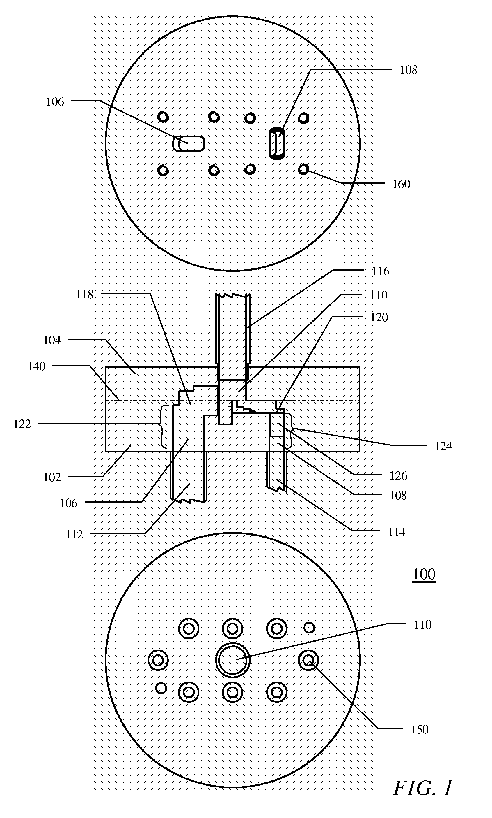
[0014]With reference to FIG. 1 an ortho-mode transducer is presented. For the sake of clarity the drawings present the invention in a very schematic way with elements and lines not essential for understanding the invention omitted.

[0015]The term “port” herein below refers to a part of a device, which allows for connecting a waveguide, but when the device is taken on its own the port functions as waveguide (waves are propagated inside the device), thus often when reference is made to a port it is meant to refer to the waveguide function of the port.

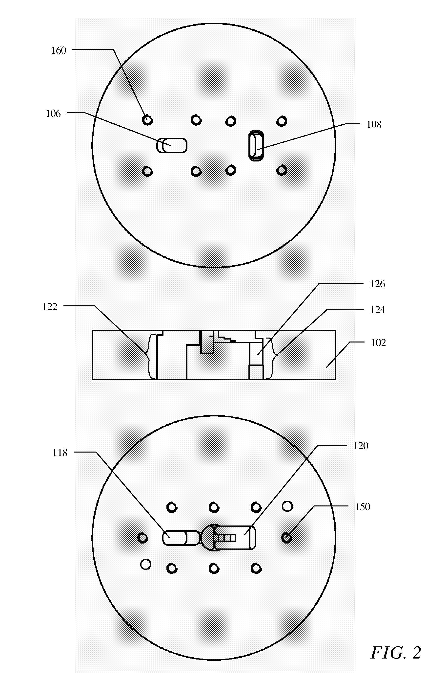
[0016]The principle of the invention is depicted in FIG. 1 through FIG. 3, which illustrate one of the plurality of possible embodiments of the present invention. The complete OMT 100 consists of two parts, 102 and 104, which can easily be realised by CNC milling techniques. A three-port branching region is used for the separation of the two polarisations. Two rectangular waveguides, a first rectangular waveguide 112 and a second rectangul...


PUM


Abstract

An ortho-mode transducer (100) comprising a first part (102) with a first port (106) for connecting a first rectangular waveguide (112) and a second port (108) for connecting a second rectangular waveguide (114). The signals in the two waveguides have orthogonal polarizations. The transducer also comprises a second part (104) with a third port (110)for connecting a common circular waveguide (116) in which the two orthogonal signals can be propagated. Symmetry axes of cross sections of the first and the second waveguides have orthogonal orientation. The first rectangular port (106) has its broad walls perpendicular to the circumference of the common circular waveguide (116) and the second rectangular port (108) has its broad walls alongside the circumference of the common circular waveguide. The first and second ports are connected to the third port in opposite positions via 90-degree bends (118, 120). In a coupling region a separating plate extends from a wall closing the common circular waveguide, wherein the separating plate is oriented perpendicular to the longitudinal axes of parts of the rectangular ports coupled to the common circular waveguide.

Description

FIELD OF THE INVENTION[0001]The present invention relates in general to the field of waveguide devices and in particular to the field of ortho-mode transducers.BACKGROUND OF THE INVENTION[0002]Ortho-mode transducer (OMT) is a device forming part of an antenna feed, which is used to combine or separate orthogonally polarized signals. In practice it is a three port waveguide device, where two of these ports are for transmitting signals dedicated to the orthogonal orientations and the third port is for connecting waveguide for transmitting combination of the two orthogonally polarized signals.[0003]Different OMT types are known e.g. from J. Uher, et. al. ‘Waveguide Components for Antenna Feed Systems: Theory and CAD’, Artech House, Boston-London, 1993. All types that provide reasonable characteristics exhibit interface ports that extend in different planes having an alignment of 90 or 180 degree to each other. There have been only two (theoretical) principle types (see FIG. 3.8.12c and...

Claims


Application Information

Patent Timeline
Patent Type & Authority Applications(United States)
IPC IPC(8): H01P5/12H01P1/161
CPCH01P1/161
Inventor ROSENBERG, UWEMAHR, ULRICHEBINGER, JURGEN
Owner TELEFON AB LM ERICSSON (PUBL)
Why Eureka
Try Eureka