
Display apparatus and control method of the same

Inactive Publication Date: 2009-12-10
SAMSUNG ELECTRONICS CO LTD
View PDF2 Cites 12 Cited by
  • Summary
  • Abstract
  • Description
  • Claims
  • Application Information

AI Technical Summary

Benefits of technology

[0008]Accordingly, it is an aspect of the present invention to provide a display apparatus and a control method of the same, in which a motion blur and a flicker are decreased.
[0009]Another aspect of the present invention is to provide a display apparatus and a control method thereof, in which brightness is enhanced.
[0018]The signal controller may reduce difference in brightness between neighboring video signals corresponding to boundaries of the image blocks.
[0033]The generating the first sub-frame may include: reducing difference in brightness between neighboring video signals corresponding to boundaries of the image blocks.

Problems solved by technology

Such a driving method reduces the image blurring phenomenon that occurs in the display apparatus, but the black screen causes the brightness of an image to be decreased and a flicker to be generated due to difference in the brightness between neighboring frames.

Method used


Image

  • Display apparatus and control method of the same
  • Display apparatus and control method of the same
  • Display apparatus and control method of the same

Examples


first embodiment

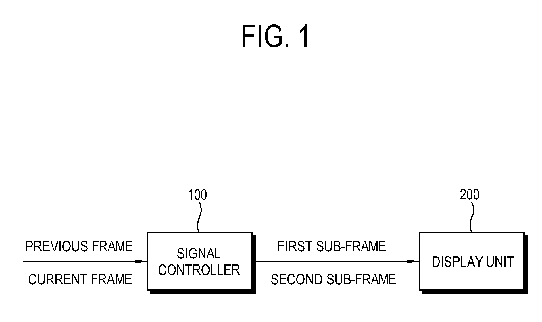
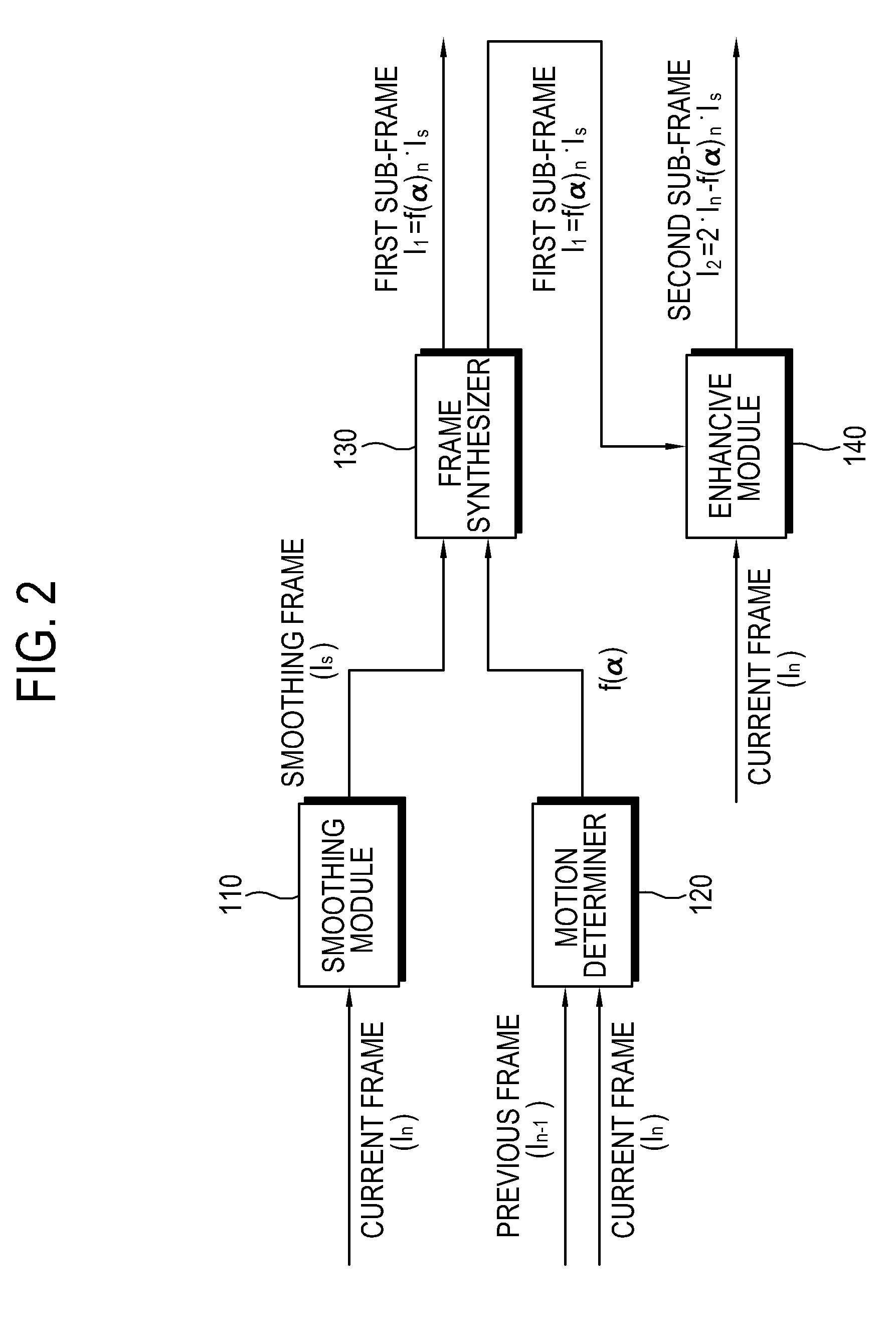
[0045]FIG. 1 is a control block diagram of a display apparatus according to the present invention, and FIG. 2 is a detailed control block diagram of a signal controller of FIG. 1.

[0046]As shown therein, a display unit 200 may include a liquid crystal display (LCD) panel including a liquid crystal layer, or an organic light emitting display (OLED) panel including an organic light emitting diode. The LCD panel or the OLED panel gives the display apparatus a hold-type characteristic of displaying a continuous image during one frame. In the case of the hold-type display apparatus, a video signal is maintained for a predetermined time if once it is input. Thus, the hold-type display apparatus is easier to have problems of an image blurring phenomenon and a residual image than an impulsive-type display apparatus.

[0047]The signal controller 100 determines motion in a current frame on the basis of previous and current frames that are successively input, and generates a plurality of sub-fram...

second embodiment

[0074]FIG. 7 is a control block diagram of a signal controller according to the present invention, and FIG. 8 illustrates frames according to FIG. 7.

[0075]As shown therein, the signal controller 101 includes two smoothing modules 111, 150, two frame synthesizers 131, 160, and two enhancive modules 141, 170. A first smoothing module 111, a first frame synthesizer 131 and a first enhancive module 141 of the second embodiment are substantially equivalent to the smoothing module 110, the frame synthesizer 130 and the enhancive module 140 of FIG. 2. That is, the signal controller 101 according to the present embodiment is provided by duplicating the configuration of FIG. 2.

[0076]The second sub-frame I2 is output from the first enhance module 141 to a second smoothing module 150, and undergoes substantially the same image process as the current frame In. A second smoothing module 150 generates an additional smoothing frame Is′ to remove the high frequency of the second sub-frame I2, and a...


PUM


Abstract

A display apparatus includes: a display unit which displays an image; and a signal controller which determines a motion state of a current frame on the basis of a previous frame and the current frame input in sequence, generates a first sub-frame of which brightness is varied according to the motion state of the current frame, generates at least one second sub-frame to compensate the brightness of the first sub-frame on the basis of the first sub-frame and the current frame, and controls the first sub-frame and the second sub-frame to be displayed on the display unit in sequence.

Description

CROSS-REFERENCE TO RELATED APPLICATION[0001]This application claims priority from Korean Patent Application No. 10-2008-0053787, filed on Jun. 9, 2008 in the Korean Intellectual Property Office, the disclosure of which is incorporated herein by reference.BACKGROUND OF THE INVENTION[0002]1. Field of Invention[0003]Apparatuses and methods consistent with the present invention relate to a display apparatus and a control method of the same, and more particularly to a hold-type display apparatus and a control method of the same.[0004]2. Description of the Related Art[0005]A display apparatus may be classified into a hold type where an image is successively displayed during one frame and an impulsive type where an image is displayed only for a short time of scanning a video signal within one frame. As an example of the impulsive-type display apparatus, there is a cathode ray tube (CRT). On the other hand, a liquid crystal display (LCD) having a liquid crystal layer, and an organic light e...

Claims


Application Information

Patent Timeline
IPC IPC(8): H04N5/57
CPCG09G3/2025G09G3/3225G09G3/3648G09G2320/0247G09G2360/16G09G2320/106G09G2340/0435G09G2340/16G09G2320/0261H04N5/21
Inventor JUNG, JUN-HOCHEN, HAN-FENGSUNG, JUN-HOHA, TAE-HYEUN
Owner SAMSUNG ELECTRONICS CO LTD
Learn More