Optical component, a front/back identifying method for the optical component, and a front/back identifying device for the optical component

a technology for optical components and optical components, applied in the field of optical components, can solve the problems of optical components becoming defective, and unable to be used anymore, and achieve the effect of not hindering inspection

Inactive Publication Date: 2009-12-10
SHARP KK
View PDF13 Cites 12 Cited by
  • Summary
  • Abstract
  • Description
  • Claims
  • Application Information

AI Technical Summary

Benefits of technology

[0017]In order to overcome the problems described above, preferred embodiments of the present invention provide an optical component which comprises a polarizing base material having a polarizing plate, a protective film laminated on a front surface of the polarizing base material and a separator laminated on a back surface of the polarizing base material, of which the front or back can be easily identified, a front / back identifying method for the optical component, which is simple and by which inspections are not hindered and the separator side surface of the optical component and the protective film side surface thereof can be reliably identified without destroying or scratching the optical component, and a front / back identifying device for the optical component.

Problems solved by technology

A mistake about the front or back of the optical component when bonding the optical component to the liquid crystal cell causes the protective film on the front surface of the optical component to be mistakenly peeled off, not the separator on the back surface thereof to be peeled off.
If the protective film is once peeled off from the optical component, the peeled-off protective film cannot be neatly bonded to the optical component again due to air bubbles or dust at a bonding interface.
In addition, if a gap is formed between the protective film and the polarizing plate due to air bubbles or other objects, there is a possibility of generating air bubbles between the polarizing plate and the liquid crystal cell to be bonded, or a possibility of defective crimping due to insufficient leveling of a panel in a mounting process of drivers.
As described above, if the protective film on the optical component is mistakenly peeled off, the optical component becomes a defective and cannot be used anymore.
Accordingly, it is extremely an important issue that the separator on the optical component is reliably peeled off without a mistake about the front or back of the optical component.
However, the conventional method for identifying the front or back of the optical component by visually observing the surface of the optical component in order to identify the phase difference plate has a problem that not everyone can identify the front or back of the optical component reliably because there are great differences among individuals, for example, a worker having weak eyes cannot identify the phase difference plate.
As a result, it becomes impossible to identify the phase difference layer based on a cross-sectional configuration and the thickness by visually observing the side face of the optical component.
The method described in the Japanese Patent Application Unexamined Publication No. 2000-321422 has a problem that it takes a lot of time and work to provide the marks for identification on all of the optical components.
In addition, when the optical component becomes larger in accordance with upsizing of the liquid crystal display device, it takes a lot of time and work to detect the position of the mark for identification and to read the mark.
Further, the method has a problem that if ink of the mark is put on the optical component, the ink is reprinted on other members and soils them.
The method such that the protective film and the separator are colored in different colors and the front or back of the optical component is identified based on the difference of the colors, has a possibility that when performing an inspection of the optical component and the liquid crystal panel, the colors may hinder the inspection.
In addition, the method such that either the front surfaces or the back surfaces of the optical components are always placed face up or placed face down in the box when packing the optical components, has a possibility that even if the separator side surfaces of the optical components are always placed face up when packing the optical components, if the optical component is taken out of the box once, is set in a bonding device and is returned to the box, the optical component may be mistakenly packed upside down.
In this case, it is impossible to identify the front or back of the optical component unless the protective film or the separator is peeled off.

Method used


Image

  • Optical component, a front/back identifying method for the optical component, and a front/back identifying device for the optical component
  • Optical component, a front/back identifying method for the optical component, and a front/back identifying device for the optical component
  • Optical component, a front/back identifying method for the optical component, and a front/back identifying device for the optical component

Examples


Embodiment Construction

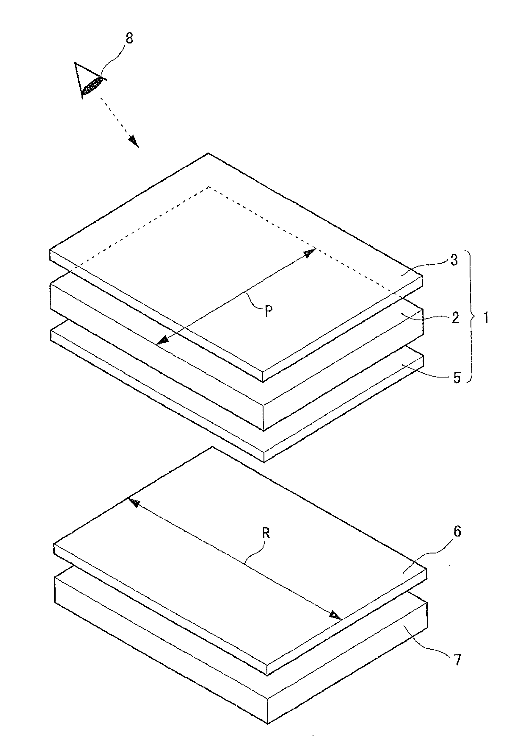
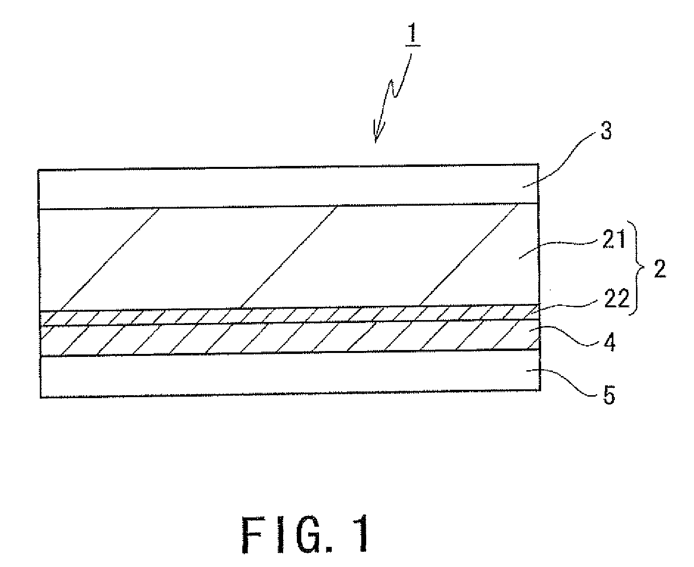
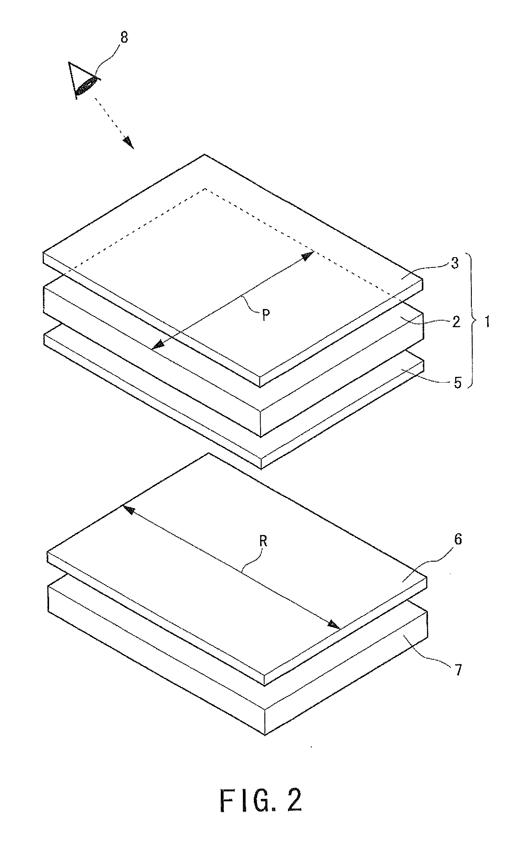
[0049]A detailed description of preferred embodiments of the present invention will now be provided with reference to the accompanying drawings. FIG. 1 is a sectional view showing one example of an optical component according to a preferred embodiment of the present invention. An optical component 1 shown in FIG. 1 includes a polarizing base material 2 provided with a polarizing plate 21, and a phase difference layer 22 on a back surface of the polarizing plate 21. A protective film 3 is laminated on a front surface of the polarizing base material 2, an adhesive layer 4 is provided on the phase difference layer 22 on a back side of the polarizing base material 2, and a separator 5 is laminated on the adhesive layer 4 on the back side of the polarizing base material 2.

[0050]It is essential only that the polarizing base material 2 of the optical component 1 according to the preferred embodiment of the present invention includes at least the polarizing plate 21. The polarizing base mat...


PUM

PropertyMeasurementUnit
thicknessaaaaaaaaaa
thicknessaaaaaaaaaa
orientation anglesaaaaaaaaaa

Abstract

An optical component including a protective film laminated on its front side and a separator on its back side, of which the front or back is easily identified, a front/back identifying method for the component, which is simple, and neither hinders other inspections nor destroys/scratches the component, and a front/back identifying device for the component.
Using the device including an analyzer 6 for an optical component 1 configured such that when a crossed Nicols arrangement is formed between the component 1 and the analyzer 6, an amount or a hue of light transmitting through the arrangement when placed in the arrangement is a protective film 3 differs from that when placed therein is a separator 5, the front or back of the component 1 is identified by observing the light to identify which film is placed in the arrangement based on the amount or the hue of the light.

Description

BACKGROUND OF THE INVENTION[0001]1. Field of the Invention[0002]The present invention relates to an optical component which includes a polarizing base material having a polarizing plate and other members, a protective film laminated on a front surface of the polarizing base material and a separator laminated on a back surface thereof, and is bonded to a liquid crystal cell at the time of assembling a liquid crystal panel, a front / back identifying method for identifying the front or back of the optical component, and a front / back identifying device used for identifying the front or back of the optical component.[0003]2. Description of the Related Art[0004]A liquid crystal panel which is generally used for a liquid crystal display device includes a liquid crystal cell in which liquid crystal is sealed in between a pair of glass substrates on which transparent electrodes and other members are provided, and an optical component having a polarizing base material, a phase difference plate...

Claims


Application Information

Patent Timeline
Patent Type & Authority Applications(United States)
IPC IPC(8): G01N21/21G02B27/28
CPCG02B5/3083G02F1/1303G02F2202/28G02F2201/50G02F2001/133311G02F1/133311
Inventor NAKAI, NOBUHIKO
Owner SHARP KK
Why Eureka
Try Eureka