General diffractive optics method for expanding an exit pupil

a general diffractive and optics technology, applied in optics, instruments, diffraction gratings, etc., can solve the problem that the display no longer qualifies as an ned

Inactive Publication Date: 2009-12-10
NOKIA CORP
View PDF1 Cites 162 Cited by
  • Summary
  • Abstract
  • Description
  • Claims
  • Application Information

AI Technical Summary

Problems solved by technology

Thus, such a display no longer qualifies as an NED, for obvious reasons.

Method used


Image

  • General diffractive optics method for expanding an exit pupil
  • General diffractive optics method for expanding an exit pupil
  • General diffractive optics method for expanding an exit pupil

Examples


Embodiment Construction

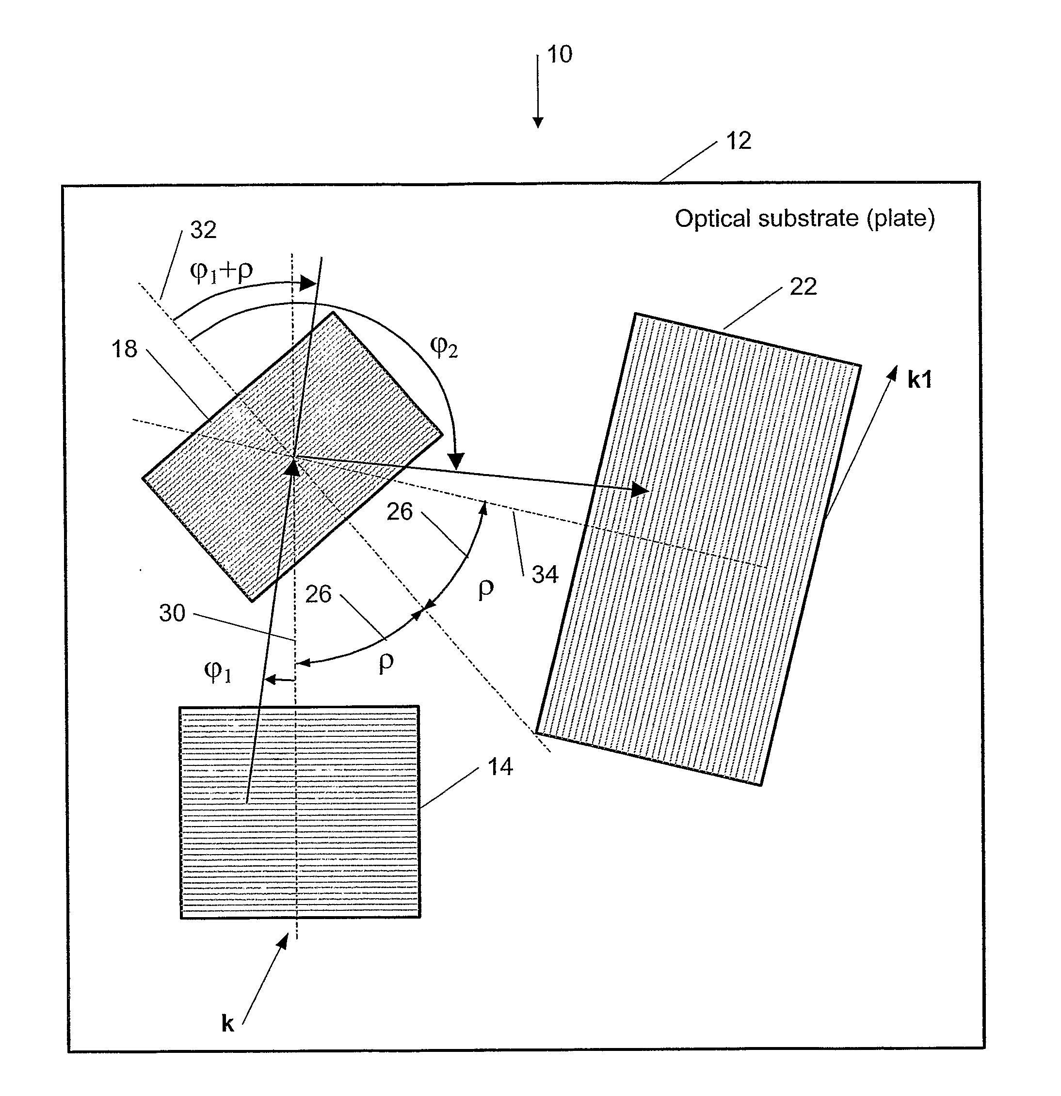
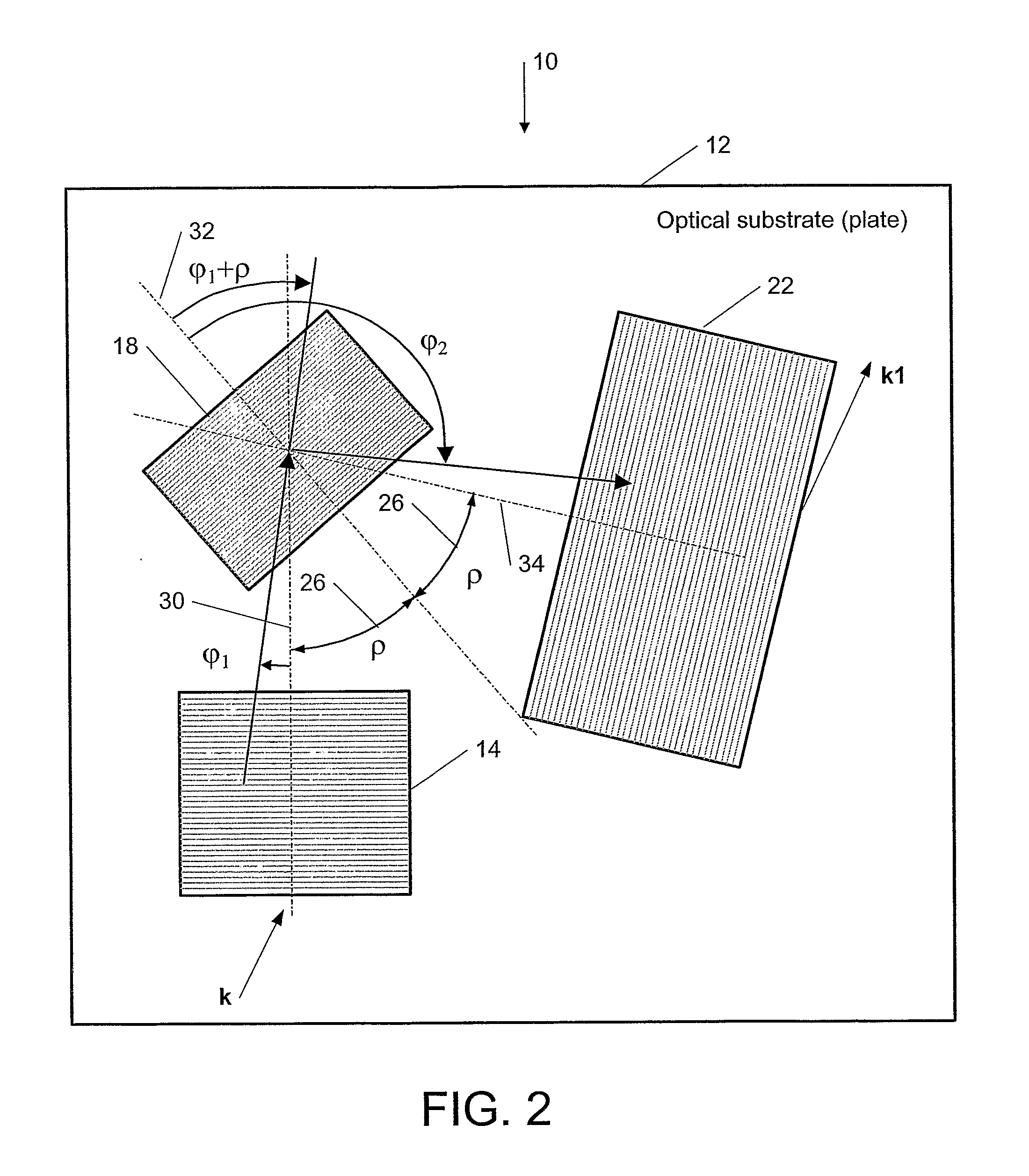
[0030]The object of the present invention is to provide a general diffractive optics method that uses a plurality of diffractive elements on an optical substrate for expanding the exit pupil of a display of an electronic device for viewing. The general diffractive optics method of the present invention can be applied to a broad optical spectral range of optical beams but most importantly to a visible part of the of optical spectrum where the optical beams are called light beams.

[0031]According to an embodiment of the present invention, this method can be used for optical coupling in an optical device and it is characterized by expanding of an exit pupil of an input optical (e.g., light) beam provided in an output optical (e.g., light) beam, wherein the optical device comprises: a substrate of optical material (or an optical substrate) having a first surface and an opposing second surface; a first (in-coupling) diffractive element disposed on the substrate for receiving an input opti...


PUM


Abstract

This invention describes a general diffractive optics method that uses a plurality of diffractive elements on an optical substrate for expanding the exit pupil of a display of an electronic device for viewing. The method can be used for optical coupling in an optical device and it is characterized by extending of an exit pupil of an input optical beam in an output optical beam wherein the optical device comprises: an optical substrate and in-coupling, intermediate and out-coupling diffractive element disposed on the optical substrates, wherein periodic lines of the intermediate diffractive element comprise an angle ρ with periodic lines of the in-coupling and of the out-coupling diffractive elements, respectively. The system can support a broad range of rotation angles (e.g., 0<ρ<70°) and corresponding conical angles and remains geometrically accurate.

Description

TECHNICAL FIELD[0001]The present invention relates generally to a display device and, more specifically, to a general diffractive optics method that uses a plurality of diffractive elements for expanding the exit pupil of a display for viewing.BACKGROUND ART[0002]While it is a common practice to use a low-resolution liquid-crystal display (LCD) panel to display network information and text messages in a mobile device, it is preferred to use a high-resolution display to browse rich information content of text and images. A microdisplay-based system can provide full color pixels at 50-100 lines per mm. Such high-resolution is generally suitable for a virtual display. A virtual display typically consists of a microdisplay to provide an image and an optical arrangement for manipulating light emerging from the image in such a way that it is perceived as large as a direct view display panel. A virtual display can be monocular or binocular.[0003]The size of the beam of light emerging from ...

Claims


Application Information

Patent Timeline
Patent Type & Authority Applications(United States)
IPC IPC(8): G02B27/44
CPCG02B5/32G02B27/0081G02B27/4205G02B27/42G02B27/0944
Inventor LEVOLA, TAPANI
Owner NOKIA CORP
Why Eureka
Try Eureka