
Communication device with a path protection function, and network system using the communication device

a communication device and path protection technology, applied in the field of communication devices, can solve problems such as unfavorable network administrator's intentions, high cost of nodes, and type that does not allow network administrator's intentions

Inactive Publication Date: 2009-12-10
HITACHI LTD
View PDF11 Cites 24 Cited by
  • Summary
  • Abstract
  • Description
  • Claims
  • Application Information

AI Technical Summary

Benefits of technology

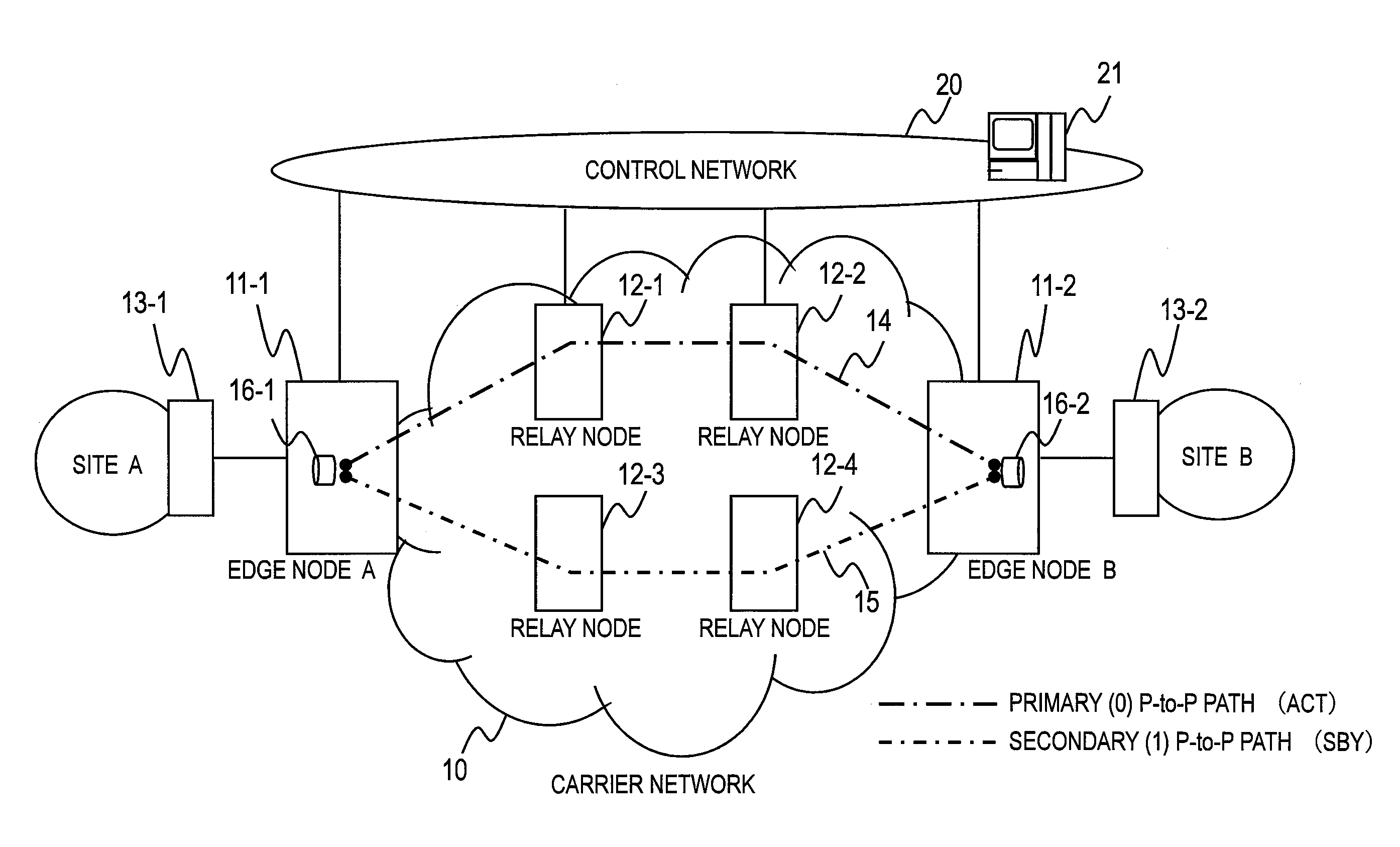
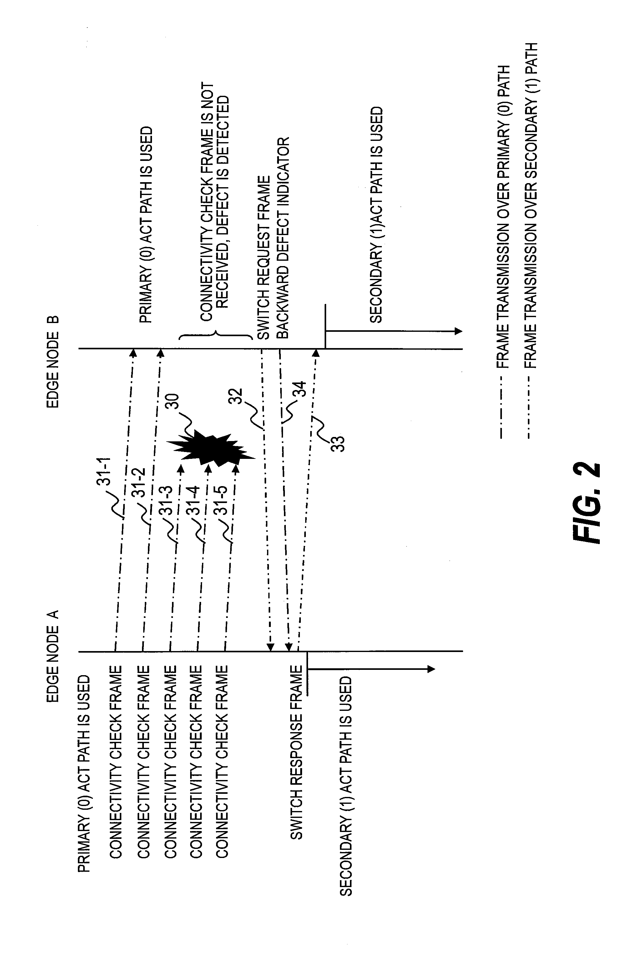
[0013]According to an aspect of this invention, two different point-to-multipoint paths are built so that, in the event of a defect, an end node that has detected the defect transmits a path switch request for a switch from the normal communication path to the auxiliary communication path to a start node via a point-to-point path. This makes it possible to notify the start node of defect information about a defect in a point-to-multipoint path, which is basically for one-way communication. A network system that switches a path used for communication only between a start node and end nodes from a normal communication path to an auxiliary communication path is thus provided.

Problems solved by technology

This gives rise to such problems as a difficulty in finding out which node a path set to bypass a defect runs through, and the uncertainty about whether or not the defect bypassing route can keep a bandwidth that has been secured by the pre-defect route.
A network of this type does not allow the network administrator's intention to be reflected on the network design.
Further, the need for every node that constitutes the network to have a defect bypassing function makes the nodes expensive.
A problem of the technology disclosed in JP 2007-282153 A is that it is a protection function limited to networks that have a ring topology and cannot be applied to tree topology networks where the start node and the end node are different nodes.
The technology of JP 2007-282153 A is not always applicable to WANs interconnecting companies whose network topologies are often of the tree type.

Method used


Image

  • Communication device with a path protection function, and network system using the communication device
  • Communication device with a path protection function, and network system using the communication device
  • Communication device with a path protection function, and network system using the communication device

Examples


Embodiment Construction

[0036]A detailed description is given below with reference to the accompanying drawings on a preferred embodiment of a network according to this invention, a communication device that constitutes the network, and protection, defect detection, and defect notification in a point-to-multipoint path. The following embodiment describes this invention taking the multiprotocol label switching (MPLS) protocol as an example. However, this invention is applicable to any protocol that builds a connection-oriented logical path to transfer frames.

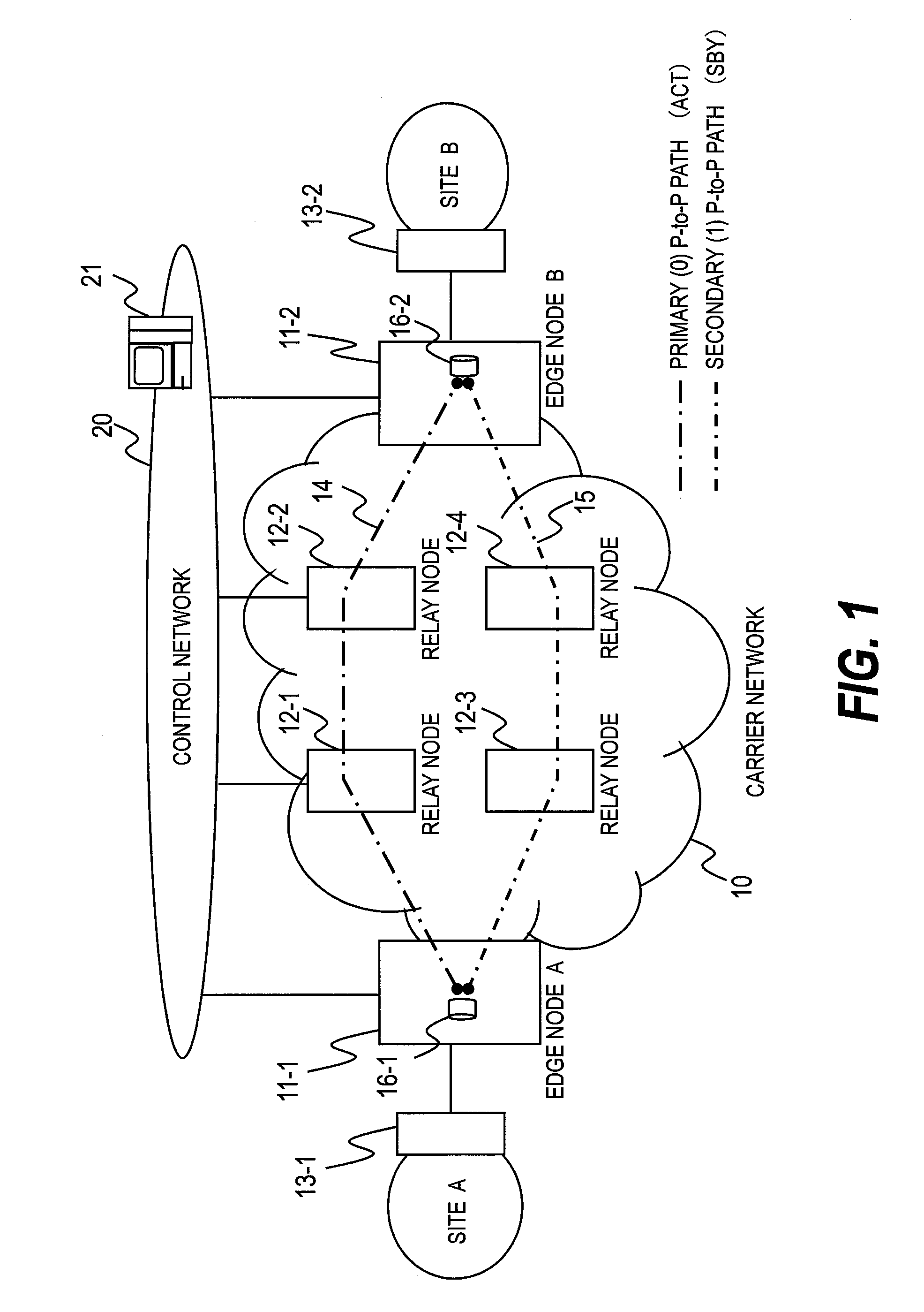
[0037]FIG. 1 is an explanatory diagram illustrating an example of a carrier network 10 according to an embodiment of this invention.

[0038]Specifically, FIG. 1 illustrates an example of the carrier network 10 in which a point-to-point logical path is set between an edge node A 11-1, which accommodates a user site A (hereinafter referred to as site A), and an edge node B 11-2, which accommodates a user site B (hereinafter referred to as site B).

[0039]The ...


PUM


Abstract

Provided is a network system including a start device and multiple end devices. A point-to-point (P-to-P) logical path is set to be used for unicast communication between the start device and each of the end devices. A first point-to-multipoint (P-to-M) logical path and a second P-to-M logical path are set to be used for multicast communication from the start device to the multiple end devices. The start device transmits data over the first P-to-M logical path. When one of the end devices detects a defect along the first P-to-M logical path, the end device that has detected the defect transmits a switch request over the P-to-P logical path set between this end device and the start device. The start device receives the switch request and transmits data over the second P-to-M logical path.

Description

CLAIM OF PRIORITY[0001]The present application claims priority from Japanese patent application JP2008-150281 filed on Jun. 9, 2008, the content of which is hereby incorporated by reference into this application.BACKGROUND OF THE INVENTION[0002]This invention relates to a communication device. More particularly, a technology disclosed herein relates to a method of notifying a defect along a point-to-multipoint logical path in multi-protocol label switching (MPLS) and other transfer protocols where a connection-oriented logical path is built, to a logical path switching method, and to a communication device that has a logical path defect notifying function and a logical path switching function.[0003]With the progress of IT and the broadening of the bandwidth of wide area networks (WANs) or metropolitan area networks (MANs), multimedia contents that are characterized by data distribution through streaming are increasing mainly among corporations as observed in, for example, a high-def...

Claims


Application Information

Patent Timeline
IPC IPC(8): H04L12/56H04L45/128H04L45/16H04L45/24H04L45/247H04L45/28H04L45/50H04L69/40
CPCH04L12/1868H04L41/0668H04L45/00H04L45/50H04L45/22H04L45/28H04L45/16
Inventor TAKASE, MASAYUKIENDO, HIDEKIUETA, TAISUKEKANNO, TAKAYUKI
Owner HITACHI LTD
Learn More