Tracking point detecting device and method, program, and recording medium

a point detection and point detection technology, applied in image analysis, image enhancement, instruments, etc., can solve the problem of placing a large load on the user, and achieve the effect of easy tracking

Inactive Publication Date: 2009-12-10
SONY CORP
View PDF13 Cites 45 Cited by
  • Summary
  • Abstract
  • Description
  • Claims
  • Application Information

AI Technical Summary

Benefits of technology

[0008]There has been found demand to allow a user to easily track a desired tracking target in a sure manner.
[0025]According to the above configurations, a user can easily track a desired tracking target in a sure manner.

Problems solved by technology

Accordingly, there has been a problem in that a great load is placed on the user.

Method used


Image

  • Tracking point detecting device and method, program, and recording medium
  • Tracking point detecting device and method, program, and recording medium
  • Tracking point detecting device and method, program, and recording medium

Examples


Embodiment Construction

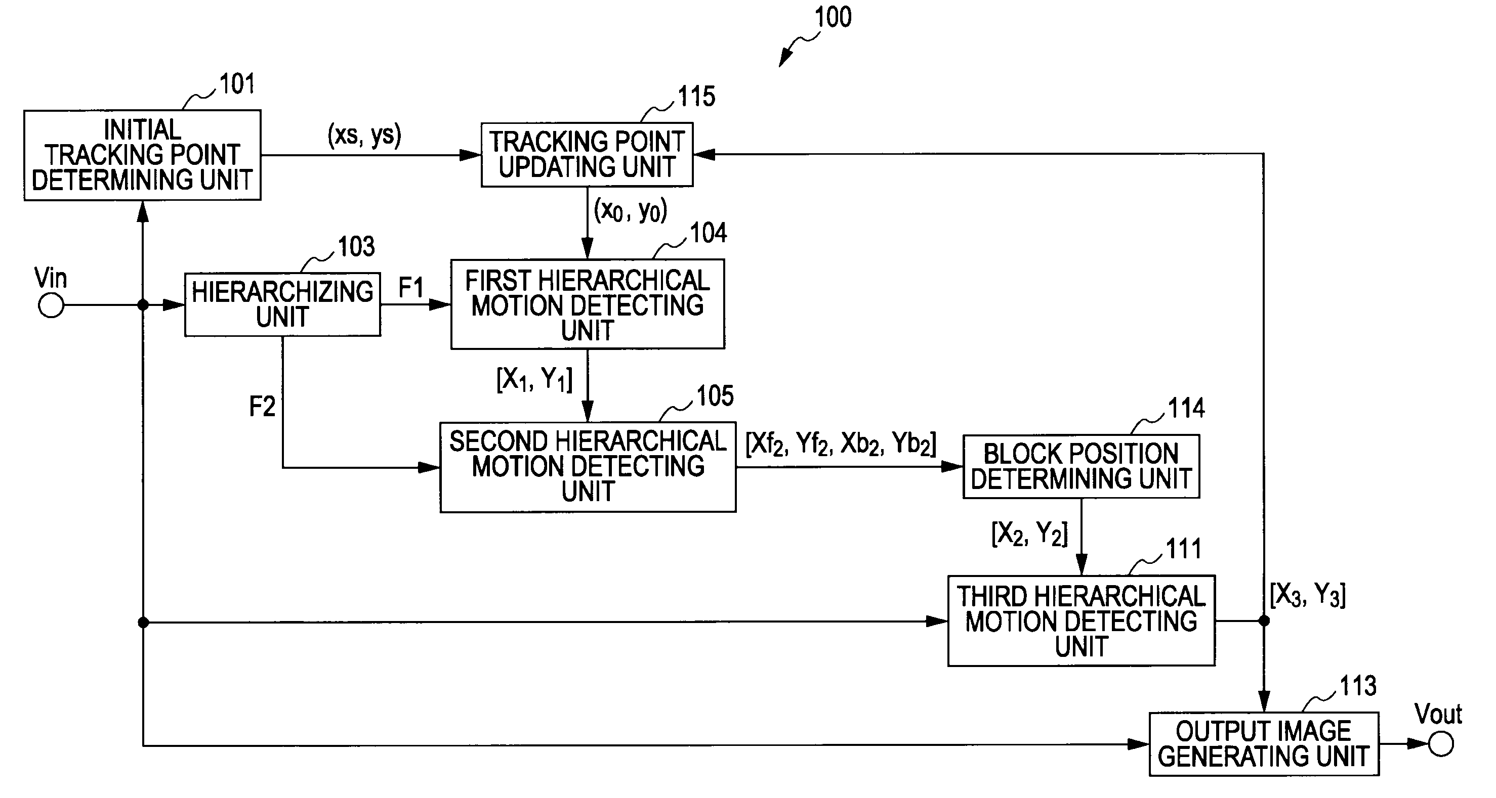
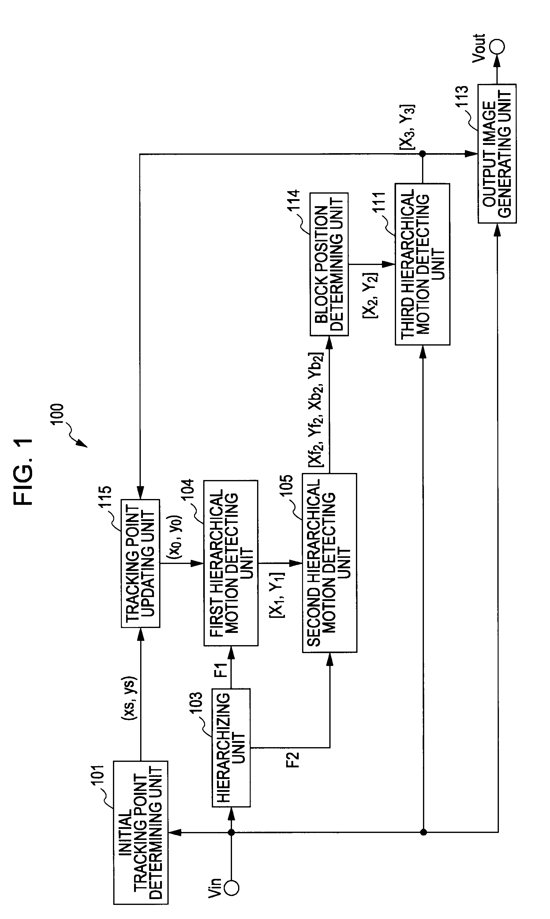
[0071]Description will be made regarding embodiments of the present invention with reference to the drawings. FIG. 1 is a block diagram illustrating a configuration example of the image processing device according to an embodiment of the present invention. With this image processing device 100, an input image signal Vin from an unshown input device is input to an initial tracking point determining unit 101, hierarchizing unit 103, third hierarchical motion detecting unit 111, and output image generating unit 113.

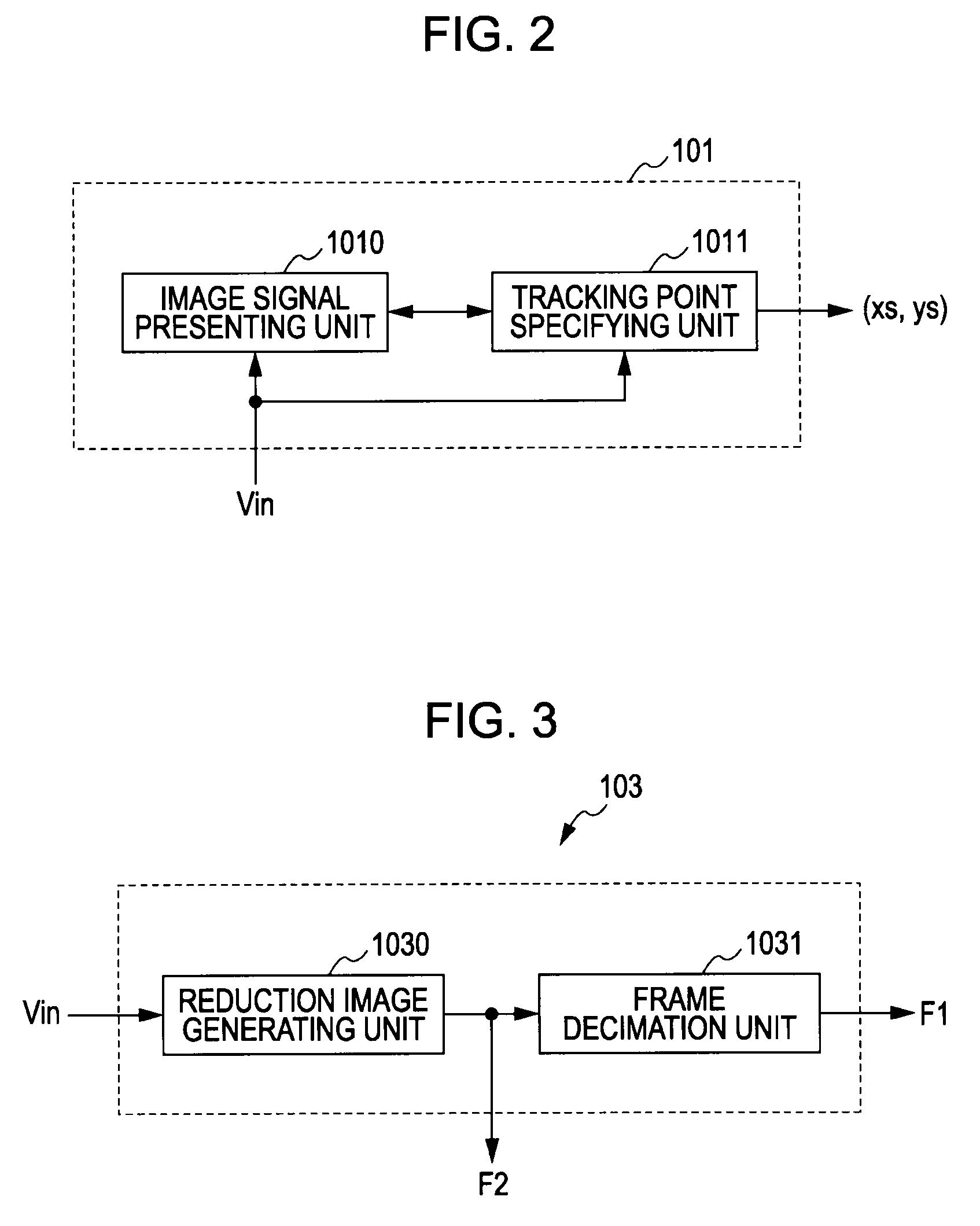
[0072]FIG. 2 is a block diagram illustrating a detailed configuration example of the initial tracking point determining unit 101. As shown in FIG. 2, the initial tracking point determining unit 101 is configured of an image signal presenting unit 1010, and tracking point specifying unit 1011.

[0073]The image signal presenting unit 1010 is configured as, for example, a display or the like so as to display an image corresponding to the input image signal Vin. The tracking point...


PUM


Abstract

A tracking point detecting device includes: a frame decimation unit for decimation the frame interval of a moving image configured of multiple frame images continuing temporally; a first detecting unit for detecting, of two consecutive frames of the decimated moving image, a temporally-subsequent frame pixel corresponding to a predetermined pixel of a temporally-previous frame; a forward-direction detecting unit for detecting the pixel corresponding to a predetermined pixel of a temporally-previous frame of the decimated moving image, at each of the decimated frames in the same direction as time; an opposite-direction detecting unit for detecting the pixel corresponding to the detected pixel of a temporally-subsequent frame of the decimated moving image, at each of the decimated frames in the opposite direction of time; and a second detecting unit for detecting a predetermined pixel of each of the decimated frames by employing the pixel positions detected in the forward and opposite directions.

Description

BACKGROUND OF THE INVENTION[0001]1. Field of the Invention[0002]The present invention relates to a tracking point detecting device and method, program, and recording medium, and specifically, a tracking point detecting device and method, program, and recording medium which allow a user to track a desired tracking target easily and in a sure manner.[0003]2. Description of the Related Art[0004]Heretofore, there have been a great number of techniques for tracking a target specified by a user within a moving image, and the technique in Japanese Unexamined Patent Application Publication No. 2005-303983 has been proposed, for example.[0005]With the technique in Japanese Unexamined Patent Application Publication No. 2005-303983, a method has been employed wherein the motion of a tracking target specified first is detected, and a tracking point is moved according to the motion thereof. Therefore, there has been a problem wherein when a tracking target involves rotation or deformation, the m...

Claims


Application Information

Patent Timeline
Patent Type & Authority Applications(United States)
IPC IPC(8): G06K9/00
CPCG06T7/204G06T2207/20016G06T2207/10016G06T7/248
Inventor KONDO, TETSUJIROYAMAMOTO, SAKON
Owner SONY CORP
Why Eureka
Try Eureka