Terminal box for fiberoptic cables and panel

a technology for fiberoptic cables and terminal boxes, applied in the direction of optics, instruments, optical light guides, etc., can solve the problem that the terminal boxes do not have a fastening structure, and achieve the effect of reducing warehousing costs

Inactive Publication Date: 2009-12-10
COMMSCOPE TECH LLC
View PDF22 Cites 94 Cited by
  • Summary
  • Abstract
  • Description
  • Claims
  • Application Information

AI Technical Summary

Benefits of technology

[0007]In this regard, the terminal box for fiberoptic cables comprises an at least two-part housing with a lower part and a cover, the cover being arranged pivotably on the lower part, at least one receptacle for a splice, at least one feed for a fiberoptic cable and a receptacle for a coupling, the side faces of the cover and the lower part being longer than their end faces, a pivot bearing of the cover being arranged on an end face, with the result that the cover is pivoted over the end face, i.e. upwards or downwards. This has the advantage over lateral pivoting of the cover that, when there is a plurality of adjacent terminal boxes, the pivoting operation and the subsequent connection work are not impeded. Preferably, the cover is pivoted upwards.
[0009]In a further preferred embodiment, the feed for the fiberoptic cable is arranged laterally offset in the end face opposite the pivot bearing. Preferably, the receptacles for the couplings are arranged in the same end face, but arranged offset towards the other side, which means that incoming and outgoing optical fibers are physically separated from one another, which in turn facilitates the guidance of the fibers in the terminal box.
[0012]In a further preferred embodiment, the cover in the pivoted-up state has a latching position, which prevents it from unintentionally being folded down.
[0015]Preferably, the carrier is designed to be rounded off towards the pivot bearing of the cover, which in particular simplifies the guidance of the fibers and the connection to the pivot bearing.
[0018]The panel for accommodating a terminal box for fiberoptic cables comprises a carrier plate and two side parts, the carrier plate being formed with openings for accommodating fastening elements of a terminal box, the side parts having fastening structure for fastening the panel on a frame. This means that the terminal box which is usually designed for being fastened to a wall can be fastened on the panel and the panel can then be fastened on the frame. The frame is preferably in the form of a 19″ rack. This makes it possible to considerably reduce warehousing costs since, by means of the panel, the terminal box can be arranged in a simple manner on a frame. The terminal box provided can therefore be used without any great complexity in a flexible manner for wall or frame fastening operations. Further preferably, the fastening elements of the terminal box are the fastening elements for the wall fastening. The panel is preferably in the form of an integral injection-molded part.

Problems solved by technology

However, such terminal boxes do not have any fastening structure for fastening the terminal box on a 19″ frame.

Method used


Image

  • Terminal box for fiberoptic cables and panel
  • Terminal box for fiberoptic cables and panel
  • Terminal box for fiberoptic cables and panel

Examples


Embodiment Construction

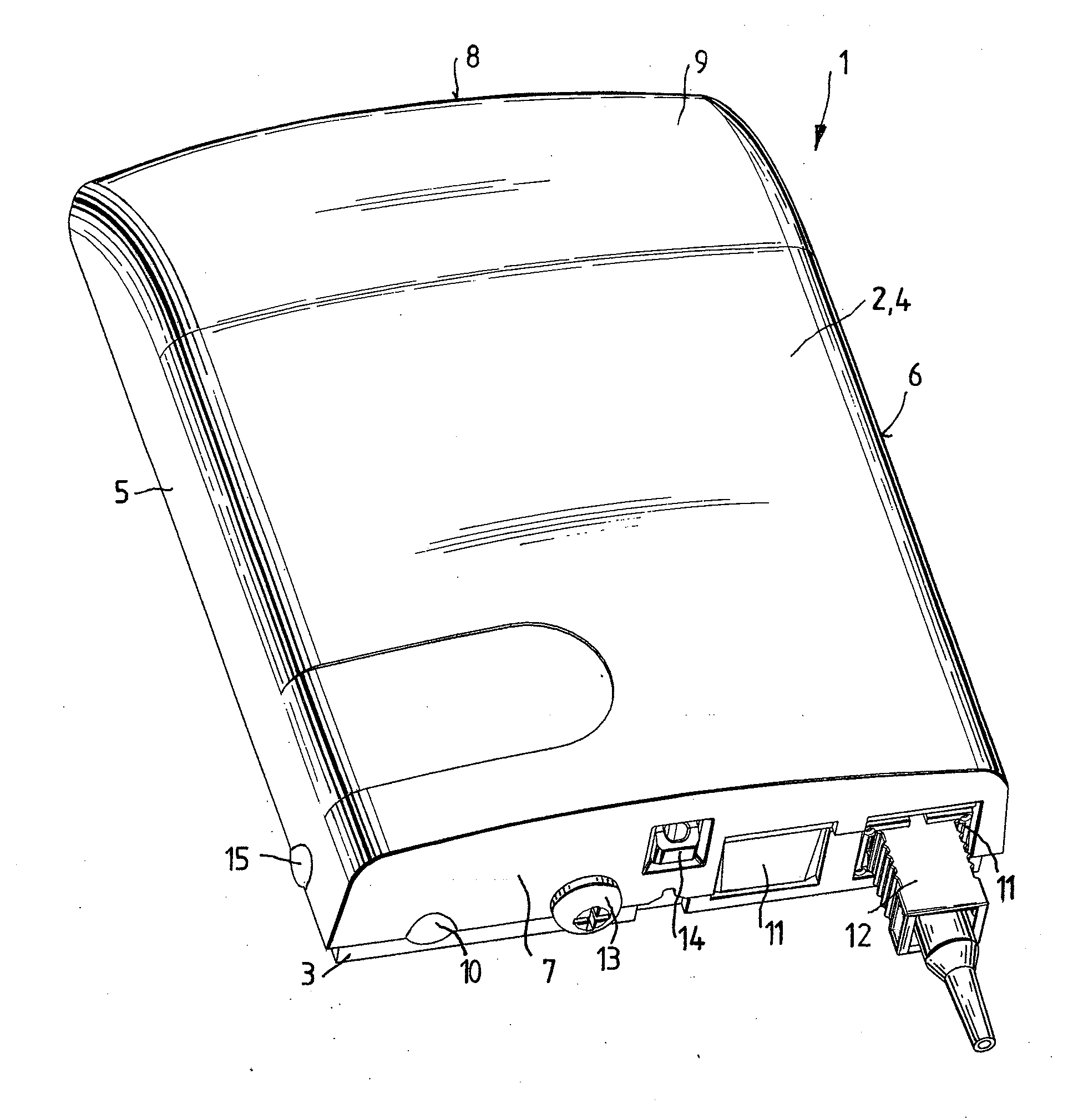
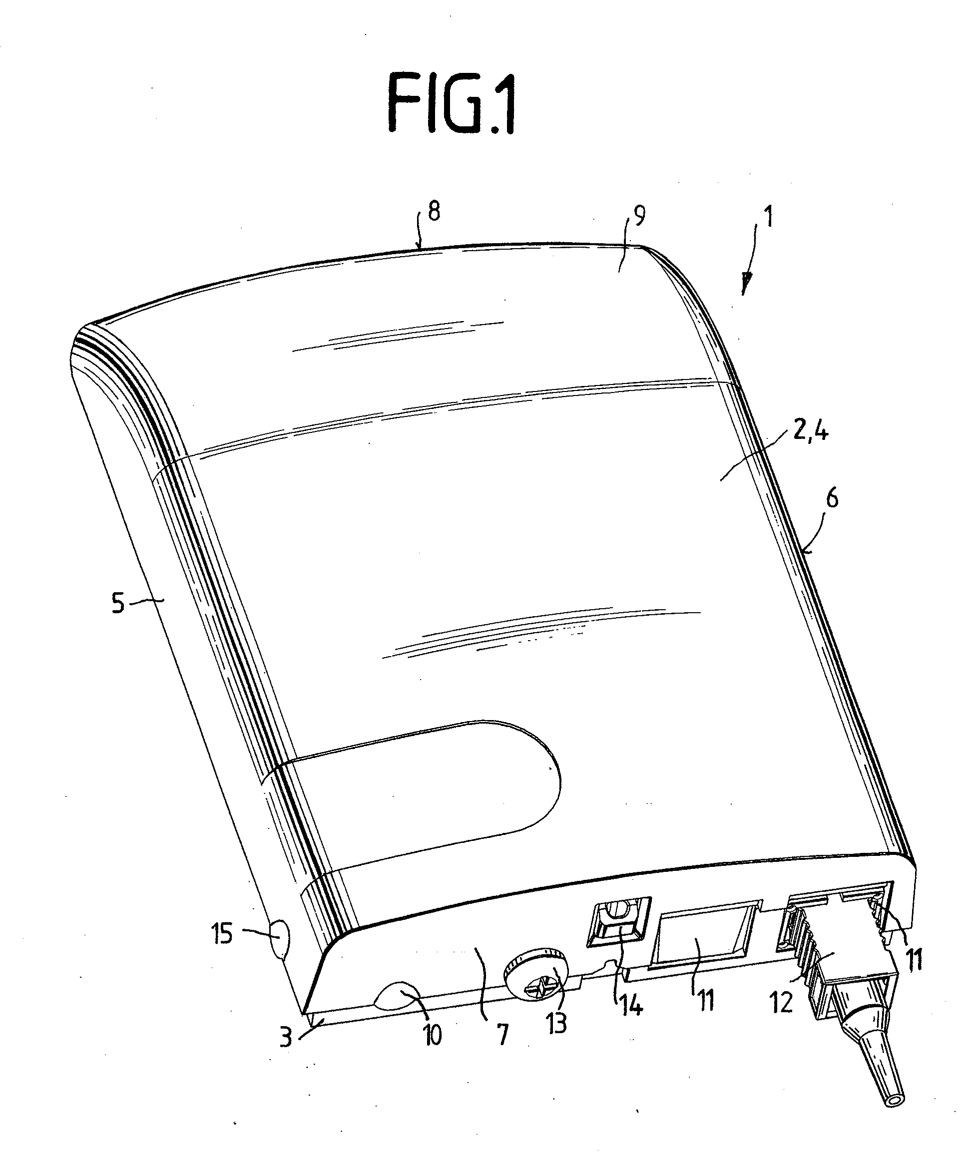
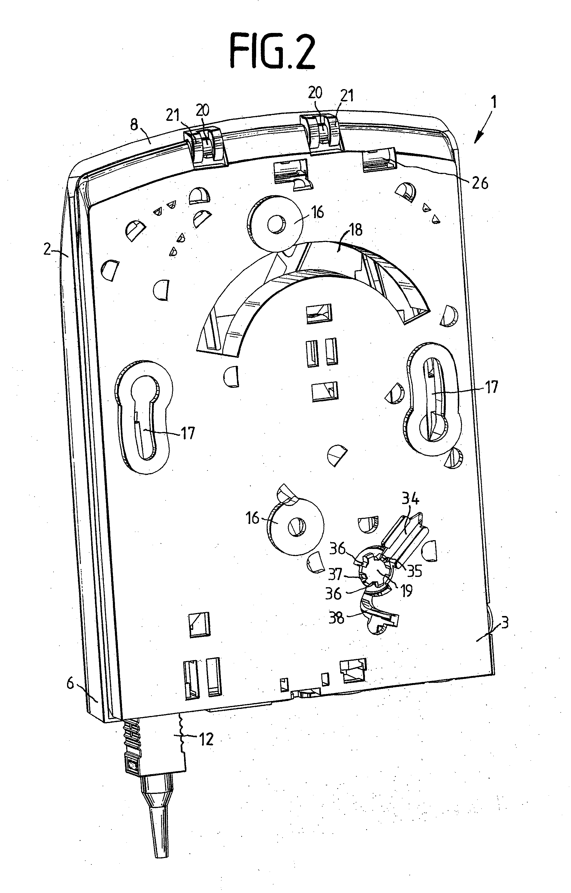
[0033]FIG. 1 illustrates a terminal box 1 for fiberoptic cables. The terminal box 1 comprises a cover 2 and a lower part 3. The cover 2 has an upper side 4, two side faces 5, 6 and two end faces 7, 8. In this case, the side faces 5, 6 are longer than the end faces 7, 8. The upper side 4 has a rounded-off region 9, with the result that the upper side 4 curves in the direction of the end face 8 towards the lower part 3, and the end face 8 has only a very low height in comparison with the end face 7. The side faces 5, 6 also taper in a corresponding manner in the direction of the end face 8. The end face 7 has a feed 10 for fiberoptic cables which is arranged such that it is laterally offset and is in a relatively deep position. On the other side, two receptacles 11 for couplings for fiberoptic plugs 12 are arranged, a fiberoptic plug having been inserted into the right-hand receptacle 11 in the illustration. Also illustrated is a securing screw 13 and a loop 14 for accommodating a lea...


PUM


Abstract

The invention relates to a terminal box (1) for fiberoptic cables, comprising an at least two-part housing with a lower part (3) and a cover (2), the cover (2) being arranged pivotably on the lower part (3), at least one receptacle for a splice, at least one feed (10) for a fiberoptic cable and a receptacle (11) for a coupling, the side faces (5, 6) of the cover (2) being longer than the end faces (7, 8) of the cover (2), a pivot bearing of the cover (2) being arranged on an end face (8) of the cover (2), and to a panel for accommodating a terminal box (1) for fiberoptic cables.

Description

[0001]This application claims benefit of Serial No. 10 2008 027 381.3, filed 9 Jun. 2008 in Germany and which application is incorporated herein by reference. To the extent appropriate, a claim of priority is made to each of the above disclosed applications.BACKGROUND OF THE INVENTION[0002]The invention relates to a terminal box for fiberoptic cables and to a panel for accommodating a terminal box.[0003]Such terminal boxes, also referred to as termination boxes, are used for connecting fiberoptic cables. For this purpose, for example, a fiberoptic cable with two fibers is spliced in each case with one pigtail, the plugs of the pigtails each being plugged into a coupling. Then, an external fiberoptic plug can be plugged via the other side of the coupling for tapping purposes.[0004]The housings of such terminal boxes generally have a lower part and a cover, the cover being articulated pivotably on the lower part, the basic shape of the housings being rectangular and the side faces bei...

Claims


Application Information

Patent Timeline
Patent Type & Authority Applications(United States)
IPC IPC(8): G02B6/00
CPCG02B6/4455G02B6/445
Inventor ADOMEIT, JORGHARTMANN, OLIVERHETZER, ULRICHKOPF, PIAMOSSNER, FRANKSIELAFF, MICHAEL
Owner COMMSCOPE TECH LLC
Why Eureka
Try Eureka