Cyclone dust-collecting apparatus

a dust-collecting apparatus and cyclone technology, applied in the direction of centrifuges, cleaning filter means, separation processes, etc., can solve the problems of weakening the suction force, inconvenience and difficulty for users other than engineers to disassemble a conventional cyclone dust-collector, so as to facilitate the separation of a cyclone uni

Inactive Publication Date: 2009-12-10
SAMSUNG ELECTRONICS CO LTD
View PDF0 Cites 77 Cited by
  • Summary
  • Abstract
  • Description
  • Claims
  • Application Information

AI Technical Summary

Benefits of technology

[0008]The present disclosure has been developed in order to solve the above described and other problems in the related art. Accordingly, an aspect of the present disclosure is to

Problems solved by technology

Accordingly, in order to maintain and repair the cyclone unit and filter unit, a plurality of units inside the cyclone dust-collector need to be separated, which causes user inconvenience.
Additionally, it may be difficult for users other than engineers to disassemble

Method used


Image

  • Cyclone dust-collecting apparatus
  • Cyclone dust-collecting apparatus
  • Cyclone dust-collecting apparatus

Examples


Embodiment Construction

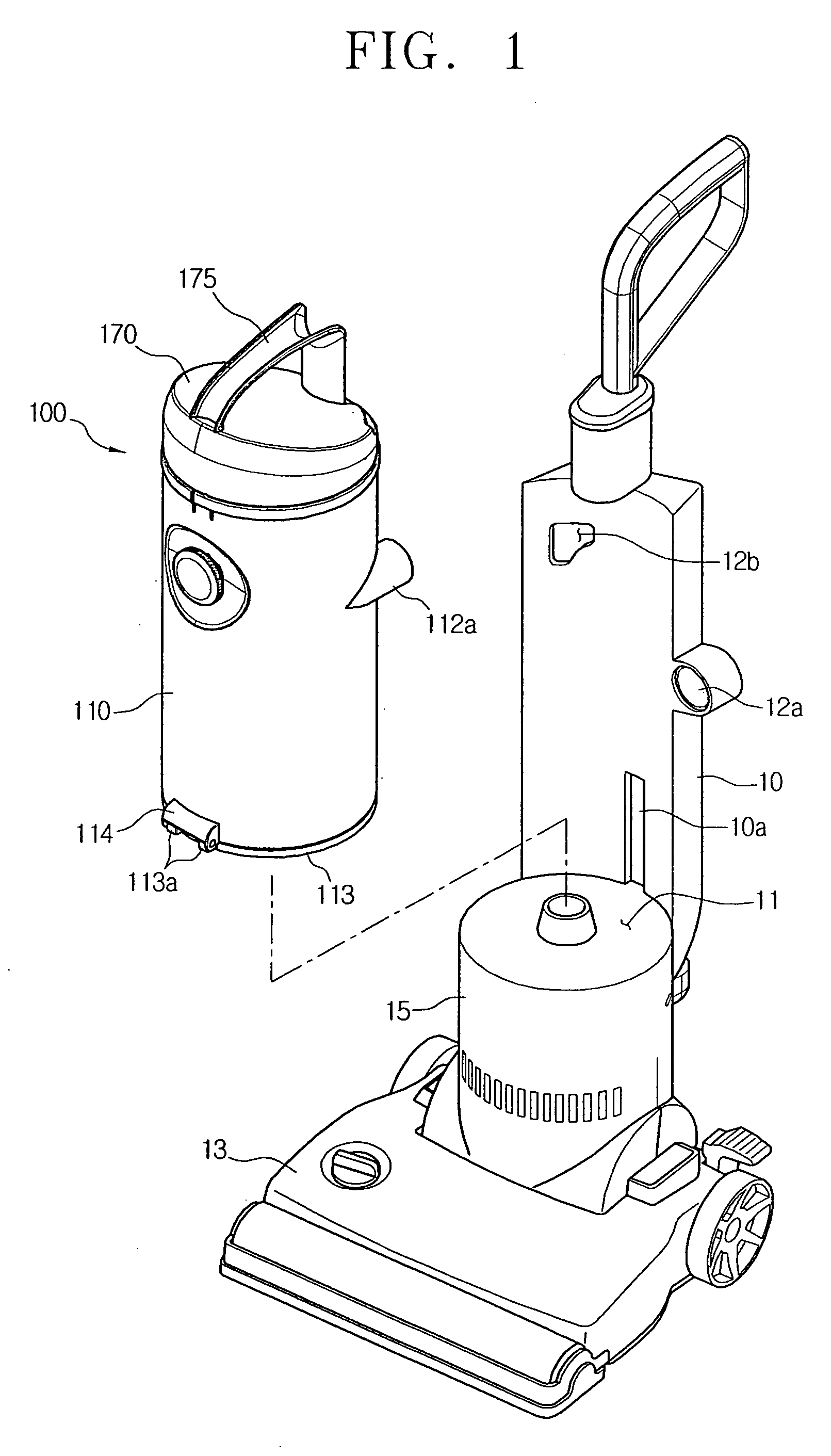
[0023]Hereinafter, a cyclone dust-collecting apparatus according to an exemplary embodiment of the present disclosure will now be described in greater detail with reference to the accompanying drawing figures.

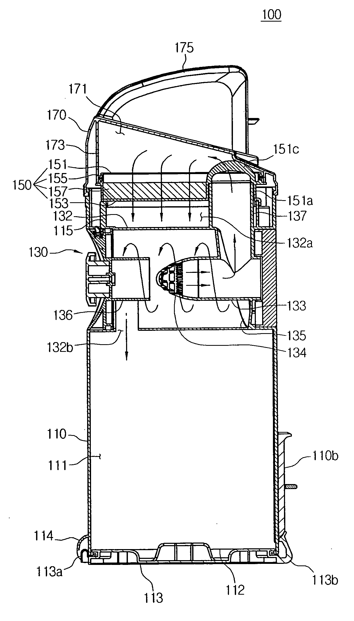
[0024]Referring to FIGS. 1 and 2, the cyclone dust-collecting apparatus 100 is detachably mounted on a mounting unit 11 of a cleaner main body 10. The cleaner main body 10 includes a main discharge port 12a to discharge dust-laden air drawn through a suction port body 13 into the cyclone dust-collecting apparatus 100, and a main inlet 12b to guide air discharged from the cyclone dust-collecting apparatus 100 towards a motor chamber 15.

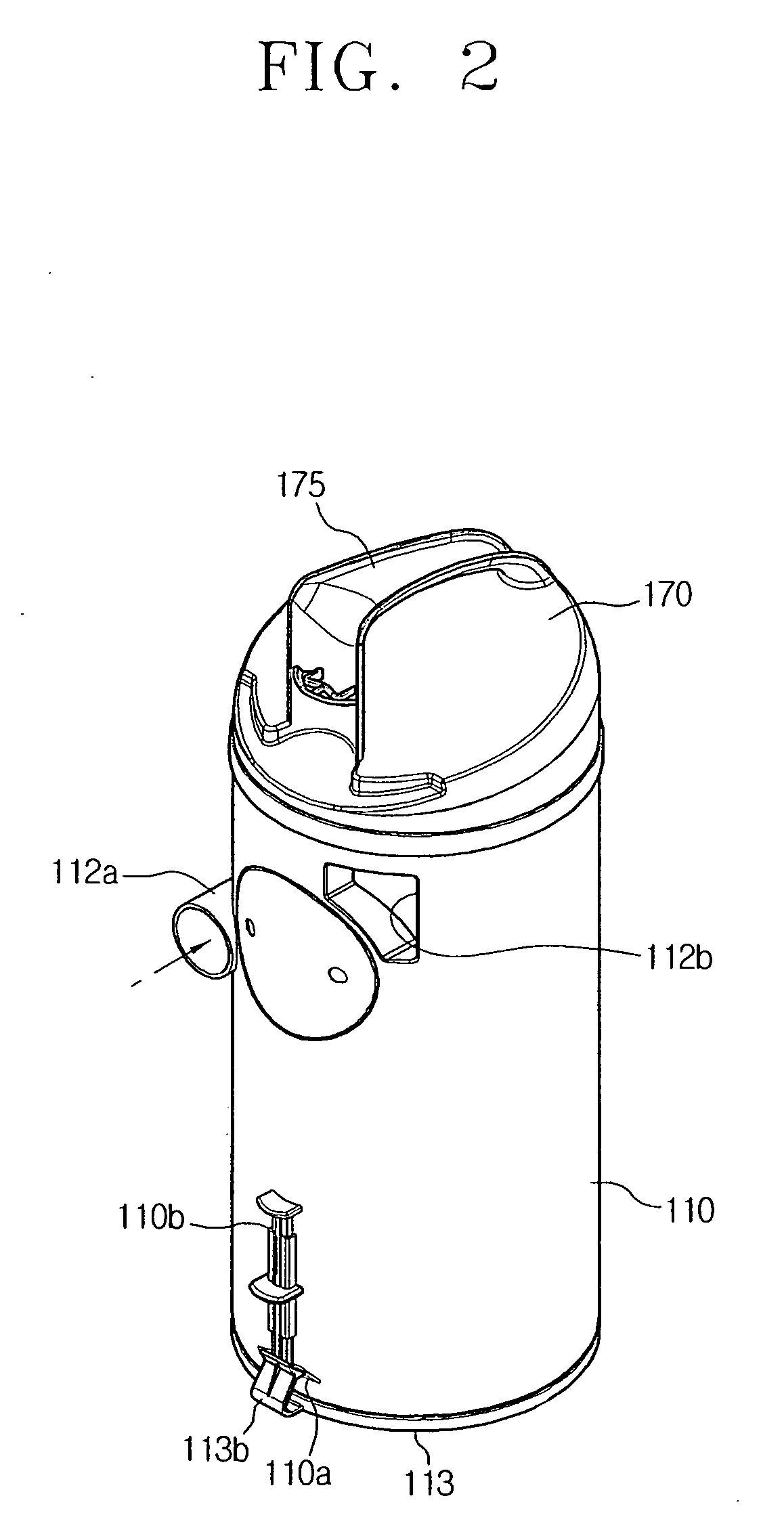
[0025]The cyclone dust-collecting apparatus 100 includes a body unit 110, a cyclone unit 130 (shown in FIG. 5), a filter unit 150, and a cover unit 170.

[0026]The body unit 110 is configured in a substantially cylindrical shape, and includes the cyclone unit 130 disposed thereinside. The body unit 110 also includes a dust-collecting chamber 111 (FI...


PUM

PropertyMeasurementUnit
Distanceaaaaaaaaaa
Circumferenceaaaaaaaaaa

Abstract

A cyclone dust-collecting apparatus includes a body unit, a top portion of which is detachably engaged with a cover unit; a cyclone unit disposed inside the body; and a filter unit detachably disposed above the cyclone unit, wherein air flowing into the body unit is guided from the cyclone unit upward to the filter unit, and is discharged downward via the filter unit.

Description

CROSS-REFERENCE TO RELATED APPLICATION[0001]This application claims the benefit under 35 U.S.C. §119 from Korean Patent Application No. 10-2008-0054336, filed on Jun. 10, 2008, in the Korean Intellectual Property Office, and the entire disclosure of which is incorporated herein by reference.BACKGROUND OF THE INVENTION[0002]1. Field of the Invention[0003]The present disclosure relates to a cyclone dust-collecting apparatus, and more particularly, to a cyclone dust-collecting apparatus to separate dust from air drawn into a cleaner main body through a suction port body, collect the separated dust, and discharge air from which dust has been separated from the cleaner main body.[0004]2. Description of the Related Art[0005]A vacuum cleaner generates a suction force using a suction motor mounted in a cleaner main body, and draws in dust or dirt along with air from a surface being cleaned through a suction nozzle using the suction force. Dust or dirt is removed from the air, while the air ...

Claims


Application Information

Patent Timeline
IPC IPC(8): B04B7/18
CPCA47L9/1608B04C2009/002A47L9/1691A47L9/1666B04C5/185A47L9/16
Inventor YOO, DONG-HUN
Owner SAMSUNG ELECTRONICS CO LTD
Why Eureka
Try Eureka