Total Knee Prosthesis and Method for Total Knee Arthroplasty

a total knee and prosthesis technology, applied in the field of total knee prosthesis and total knee arthroplasty, can solve the problems of reducing the functional ability of patients to perform activities of daily living, compromising patient's functional ability, and currently available prosthetic knee implants employed for tkr. achieve the effect of extending the tibial apertur

Active Publication Date: 2009-12-10
BLUM MICHAEL F
View PDF3 Cites 60 Cited by
  • Summary
  • Abstract
  • Description
  • Claims
  • Application Information

AI Technical Summary

Problems solved by technology

The majority of currently available prosthetic knee implants employed for TKR do not retain the natural anterior cruciate ligament.
Although the existing TKR prostheses succeed in increasing patient mobility, and provide the patient with the desired therapeutic result, at least one significant disadvantage remains.
Such abnormal translation and pivot shift often results in the patient's compromised functional abilities, such as quadriceps avoidance, and changed upper body mechanics during activities such as stair climbing and rising from a chair.
Even asymptomatic patients show gait abnormalities that could lead to reduced functional ability to perform activities of daily living over time.
Further, abnormal anterior translation of the TKR can lead to accelerated wear of the prosthesis.
The amount of bone loss that is inherent in a TKR makes a revision procedure much more difficult in the future as even more bone must be removed.
For example, U.S. Pat. No. 5,413,604 discloses a TKR prosthesis wherein the anterior cruciate ligament must be sacrificed, thereby resulting in a nonstabilized TKR with abnormal anterior translation.
Unfortunately, neither prosthesis disclosed in the '604 and '660 patents actually prevents the abnormal anterior translation of the nonstabilized TKR; or as shown in recent medical research pertaining to medial and lateral translation of ACL deficient knees, rather, they only attempt to accommodate or limit it.
As a result, the patient's functional abilities remain limited, and the prosthesis is subject to premature wear and tear.

Method used


Image

  • Total Knee Prosthesis and Method for Total Knee Arthroplasty
  • Total Knee Prosthesis and Method for Total Knee Arthroplasty
  • Total Knee Prosthesis and Method for Total Knee Arthroplasty

Examples


Embodiment Construction

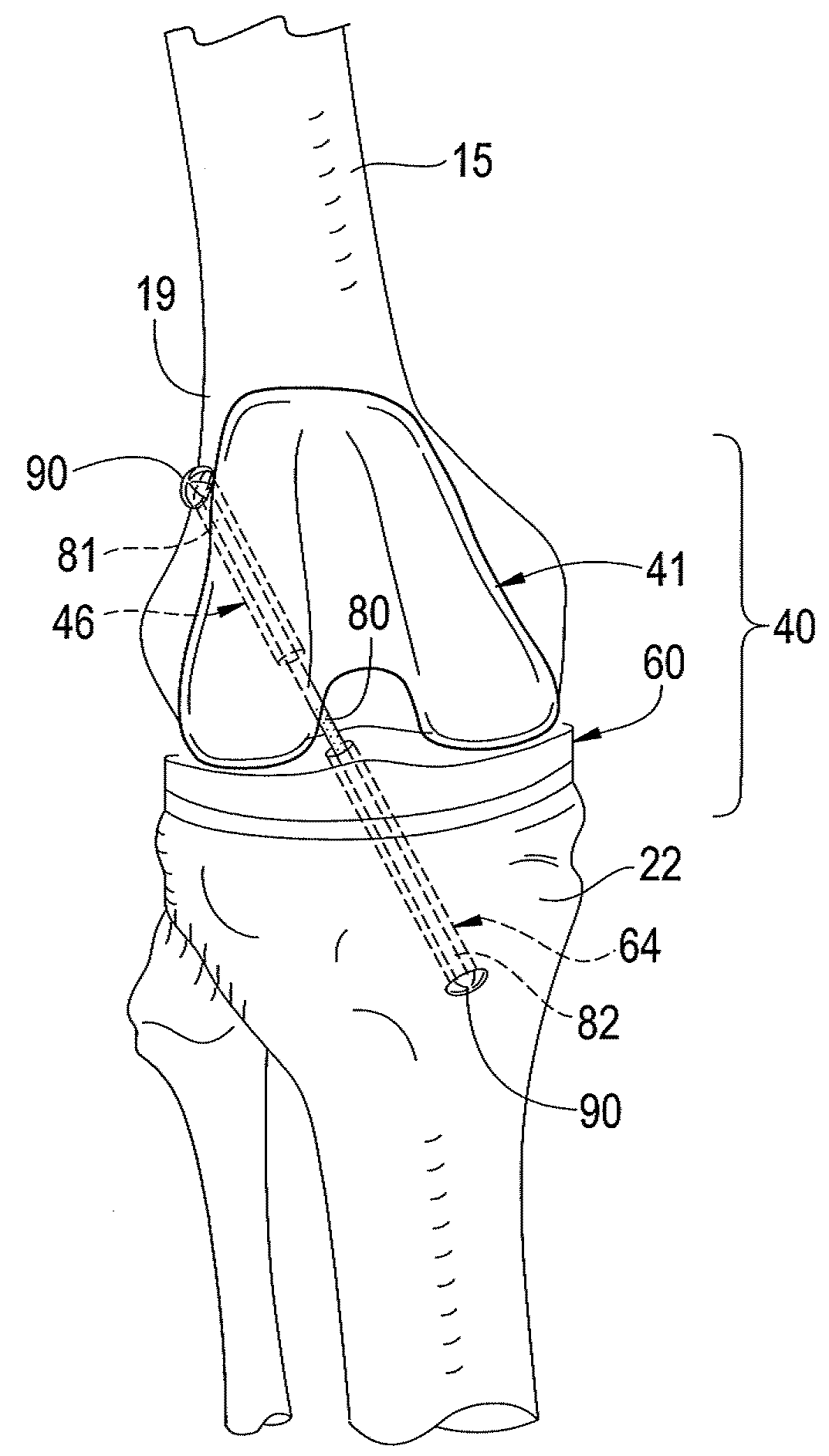
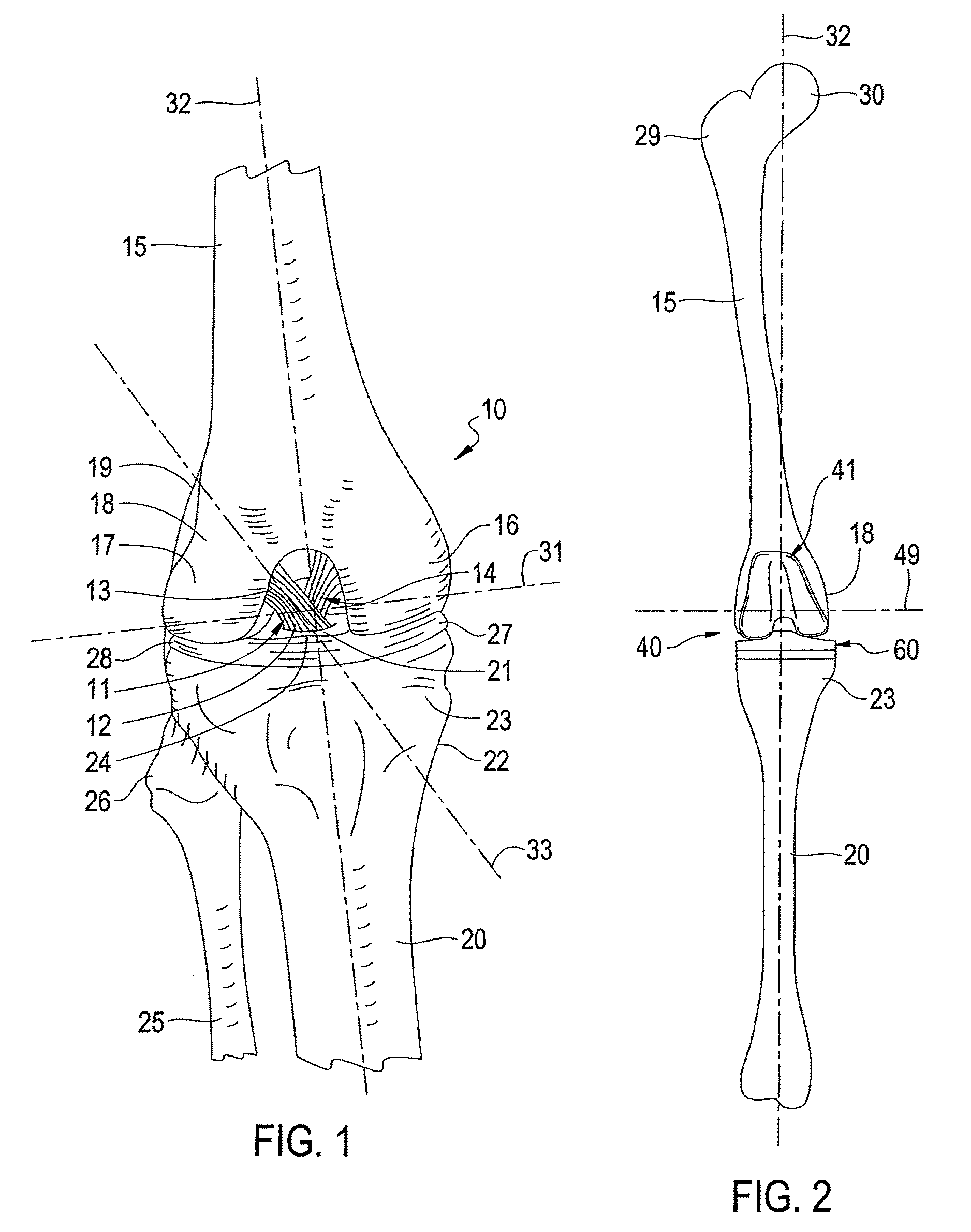
[0023]Referring to the drawings for a better understanding of the function and structure of the invention, FIG. 1 shows a typical patient's natural knee joint 10 prior to the surgical procedure. Illustrated is upper portion 23 of the tibia 20 the upper portion 26 of the fibula 25, the lower portion 18 of the femur 15, the exterior surface 19 of the femur 15, as well as the medial condyle 16 and lateral condyle 17. The anterior cruciate ligament 11 and the posterior cruciate ligament 14 are seen to be present in the knee joint 10. One end 12 of the anterior cruciate ligament 11 is attached to the anterior portion of the intercondylar eminence 21 of the tibia 20, and the second end 13 of the anterior cruciate ligament 11 is attached to the posterior portion of the medial aspect of the lateral femoral condyle 17, thereby defining an axis 33 of the anterior cruciate ligament 11. The posterior cruciate ligament 14 passes upward and forward on the medial side of the anterior cruciate liga...


PUM


Abstract

A prosthetic knee implant for implantation into a mammal, which accommodates an anterior cruciate ligament substitute to provide stability to the knee implant. The prosthetic knee implant includes a femoral component having a pair of condylar surfaces and a tibial component having a surface portion adapted to slidably engage the femoral component upon rotation of the same. The femoral component further includes a central femoral recess between the condyles providing access to the femur for drilling a channel through which a cruciate ligament substitute may be integrated into the femur. The tibial component further includes a center portion defining an aperture through which the ligament substitute maybe threaded through the tibia and integrated therein, or anchored upon its surface. Also disclosed is a method used to replace the total knee joint in a mammal with the improved prosthetic knee implant of the present invention.

Description

[0001]This application claims the benefit of filing priority under 35 U.S.C. § 119 and 37 C.F.R. §1.78 from U.S. Nonprovisional application Ser. No. 12 / 134,713 filed Jun. 6, 2008, for a Total Knee Prosthesis and Method for Total Knee Arthroplasty. All information disclosed in the prior application is incorporated herein by referenceFIELD OF INVENTION[0002]The present invention relates generally to prosthetic knee implants and corresponding surgical methods used to replace the total knee joint in a mammal. More particularly, the invention relates to a prosthetic knee implant having a femoral component and a tibial component, which are adapted to receive an anterior cruciate ligament substitute for biasing the femur and tibia together.BACKGROUND OF INVENTION[0003]Mammalian knees wear out for a variety of reasons, including inflammation from arthritis, injury, or simple wear and tear. Over the past 40 years, total knee arthroplasties (commonly referred to as total knee replacements or ...

Claims


Application Information

Patent Timeline
Patent Type & Authority Applications(United States)
IPC IPC(8): A61F2/38A61F2/08
CPCA61B17/1714A61F2/38A61B17/1764A61F2002/30604A61F2/3836
Inventor BLUM, MICHAEL F.
Owner BLUM MICHAEL F
Why Eureka
Try Eureka