
Tape measure

Inactive Publication Date: 2009-12-17
SCHRAGE SIDNEY LOUIS
View PDF15 Cites 21 Cited by
  • Summary
  • Abstract
  • Description
  • Claims
  • Application Information

AI Technical Summary

Benefits of technology

[0014]The present invention has been developed in response to the present state of the art, and in particular, in response to the problems and needs in the art that have not yet been fully solved by currently available tape measures. Accordingly, the present invention has been developed to provide a convenient and efficient one-hand operable recording tape measure.
[0016]Furthermore, the tape measure may include a magnetic locking mechanism coupled to the protective casing; wherein the magnetic locking mechanism includes a magnet configured to secure the coiled tape at a selectable distance thereby preventing lateral displacement of the measuring tape. The tape measure may also include a light module coupled to the protective casing, in communication with the magnetic locking mechanism; wherein the light module is configured to activate when the locking mechanism is actuated, thereby disposing light over a portion of the measuring tape.

Problems solved by technology

However, current tape measures typically have to be operated with two hands.
This is particular difficult to perform when the user is on a ladder fifteen feet high, in a tight area, or suspended in the air.
A type of vertigo may develop and the user may lose their equilibrium which may result in serious, if not fatal, injuries.
In addition, individuals with hand or arm defects or amputees have a difficult time in operating tape measures and then recording measurements.
The inventions heretofore known suffer from a number of disadvantages which include being limited in application, being limited in use, being difficult to use, being inconvenient, being bulky, being unduly complex, and being ineffective.

Method used


Image

  • Tape measure
  • Tape measure
  • Tape measure

Examples


Embodiment Construction

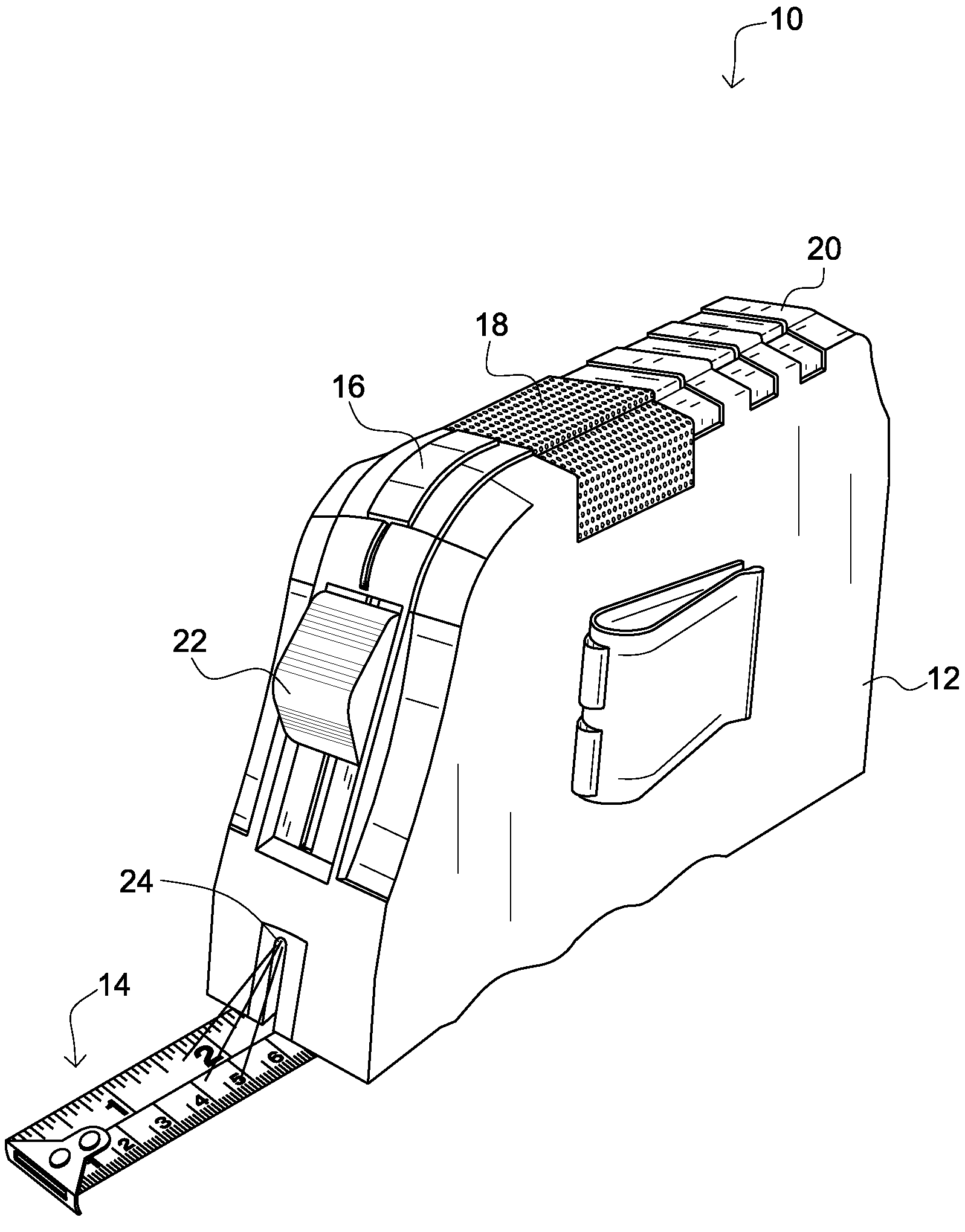
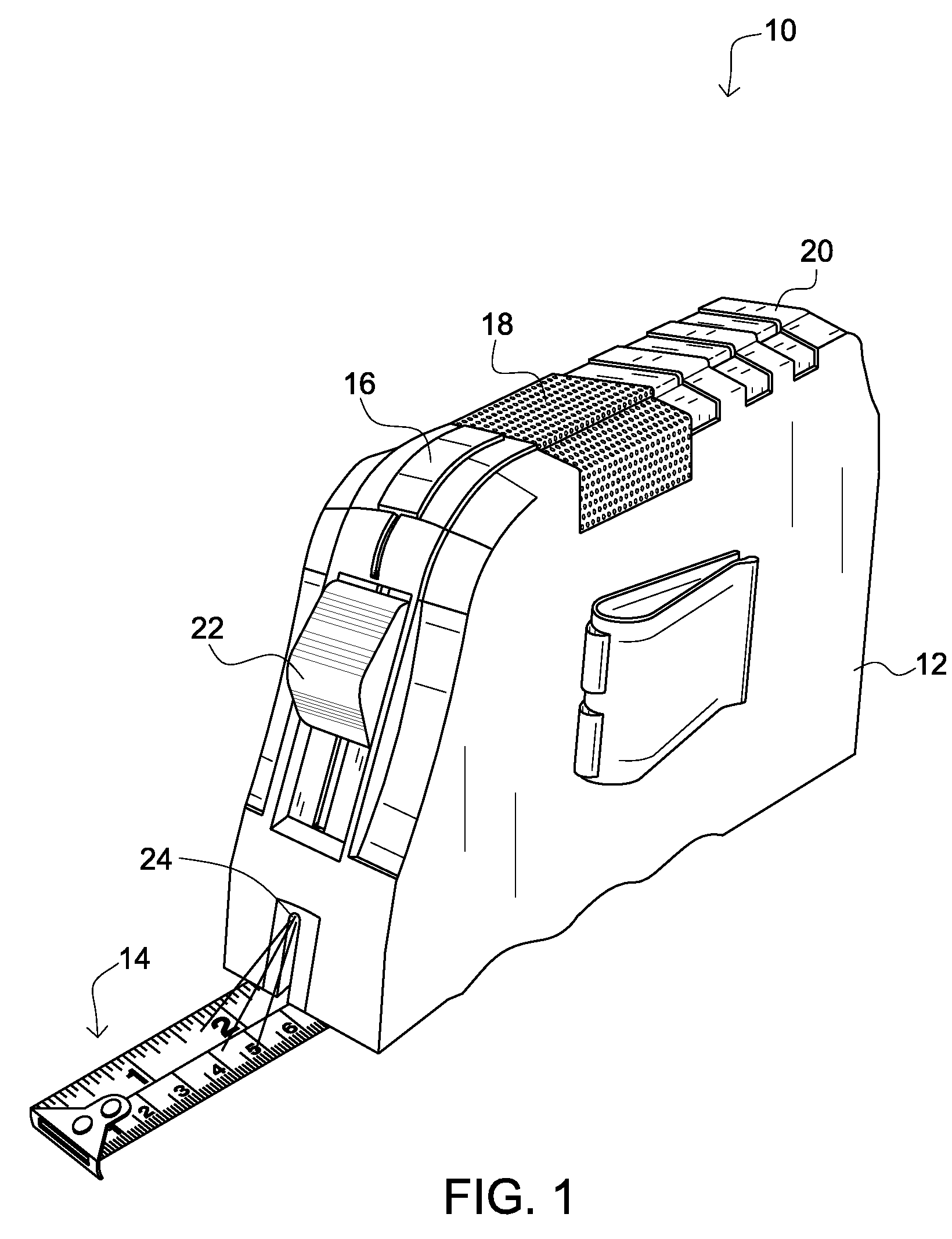
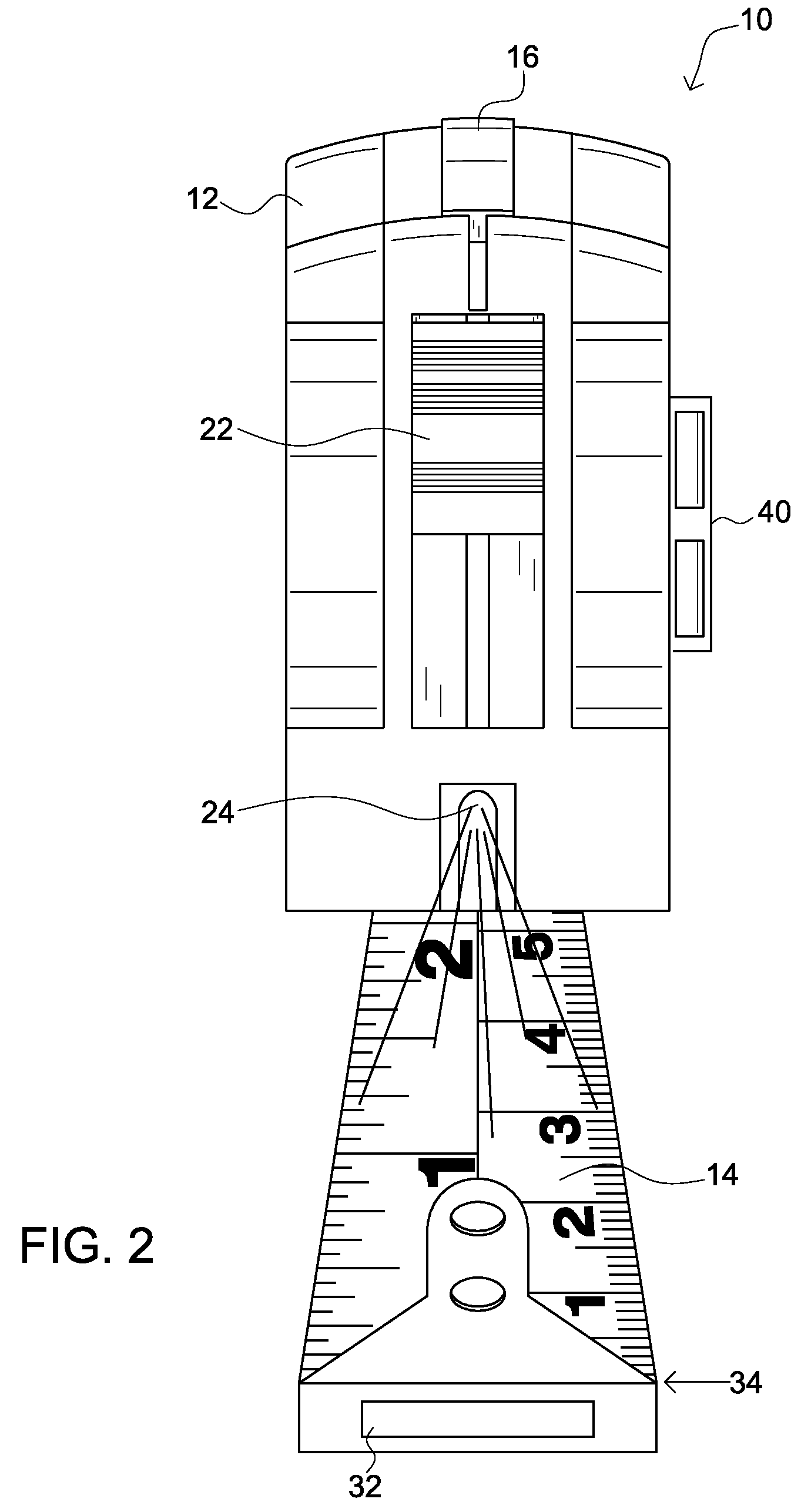
[0028]For the purposes of promoting an understanding of the principles of the invention, reference will now be made to the exemplary embodiments illustrated in the drawing(s), and specific language will be used to describe the same. It will, nevertheless, be understood that no limitation of the scope of the invention is thereby intended. Any alterations and further modifications of the inventive features illustrated herein, and any additional applications of the principles of the invention as illustrated herein, which would occur to one skilled in the relevant art and having possession of this disclosure, are to be considered within the scope of the invention.

[0029]Many of the functional units described in this specification have been labeled as modules, in order to more particularly emphasize their implementation independence. For example, a module may be implemented as a hardware circuit comprising custom VLSI circuits or gate arrays, off-the-shelf semiconductors such as logic chi...


PUM


Abstract

There is a tape measure configured for one-hand operation. The tape measure includes a protective casing and a coiled measuring tape. The tape measure includes an audio recorder and a speaker module coupled to the protective casing, wherein the speaker module is configured to audibly broadcast recorded audio information. The tape measure also includes a locking mechanism and a light module; wherein the light module is configured to activate when the locking mechanism is actuated, thereby disposing light over a portion of the measuring tape. The tape measure includes a control module in communication with each of the audio recorder, speaker module, light module, and magnetic locking mechanism, configured to provide controls thereto for each. The control module is disposed substantially above the magnetic locking mechanism on the protective housing and operable with a single digit of a hand, while the hand is grasping the protective casing.

Description

CROSS-REFERENCE TO RELATED APPLICATIONS[0001]This invention claims priority, under 35 U.S.C. §120, to the U.S. Provisional Patent Application No. 61 / 061,479 to Sidney Louis Schrage filed on Jun. 13, 2008, which is incorporated by reference herein.BACKGROUND OF THE INVENTION[0002]1. Field of the Invention[0003]The present invention relates to tape measures, specifically to a one-hand-operable recording tape measure.[0004]2. Description of the Related Art[0005]A tape measure, or measuring tape, is a flexible form of ruler. It consists of a ribbon of cloth, plastic, or metal with linear-measure markings, often in both imperial and metric units. It is a convenient, common measuring tool. Its flexibility allows for a measure of great length to be easily carried in pocket or tool kit and permits one to measure around curves or corners. However, current tape measures typically have to be operated with two hands. The user typically has to secure the locking mechanism of the tape measure and...

Claims


Application Information

Patent Timeline
IPC IPC(8): G01B3/10
CPCG01B3/1041G01B3/1082G01B3/1084G01B2003/1094G01B2003/1046G01B2003/1048G01B2003/1087G01B2003/1033G01B3/1048G01B3/1046G01B3/1094G01B3/1003
Inventor SCHRAGE, SIDNEY LOUIS
Owner SCHRAGE SIDNEY LOUIS
Learn More