

Synchronization of hysteretic power converters
- Summary
- Abstract
- Description
- Claims
- Application Information
AI Technical Summary
Benefits of technology
Problems solved by technology
Method used
Image

Examples
Embodiment Construction
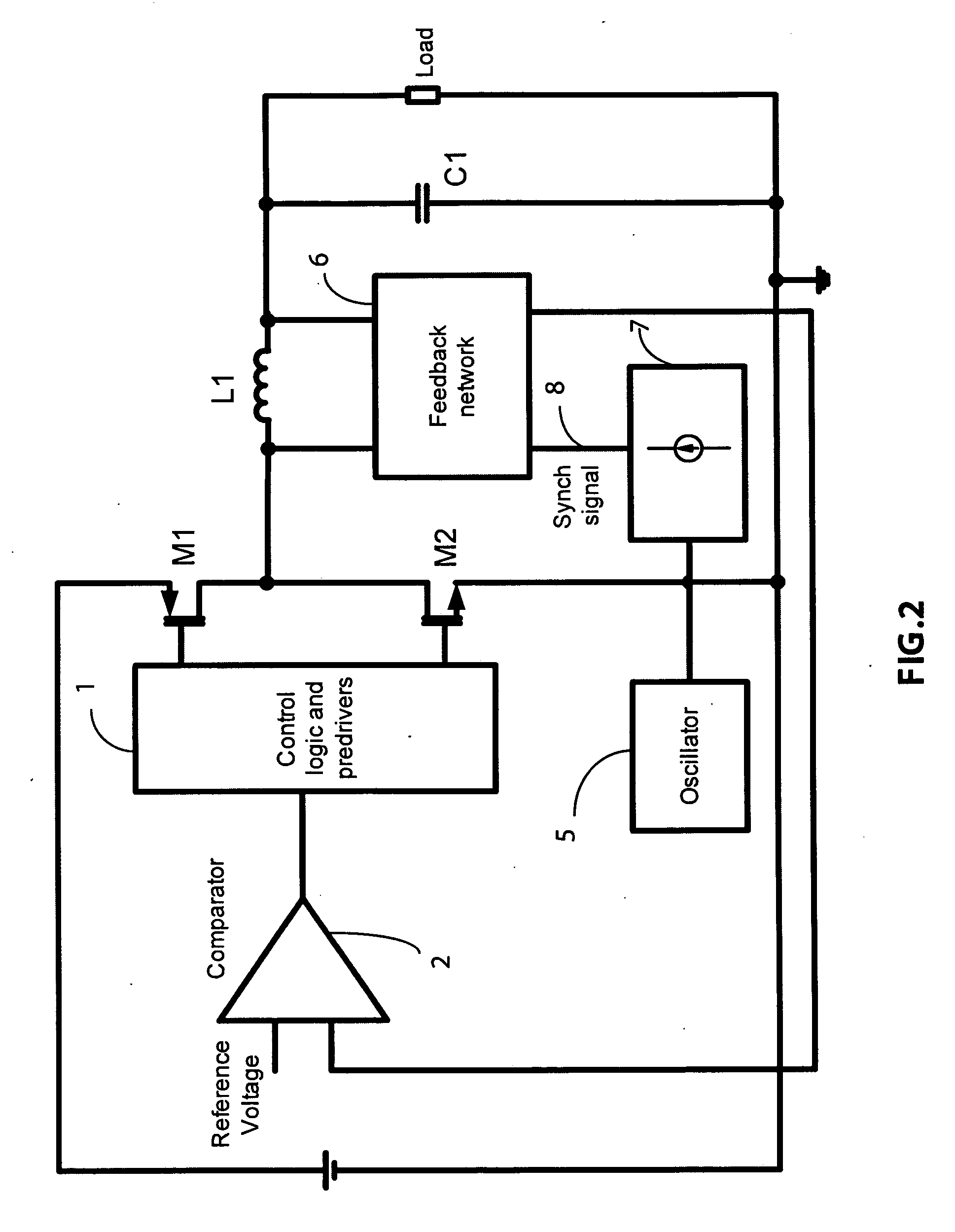
A FIG. 2
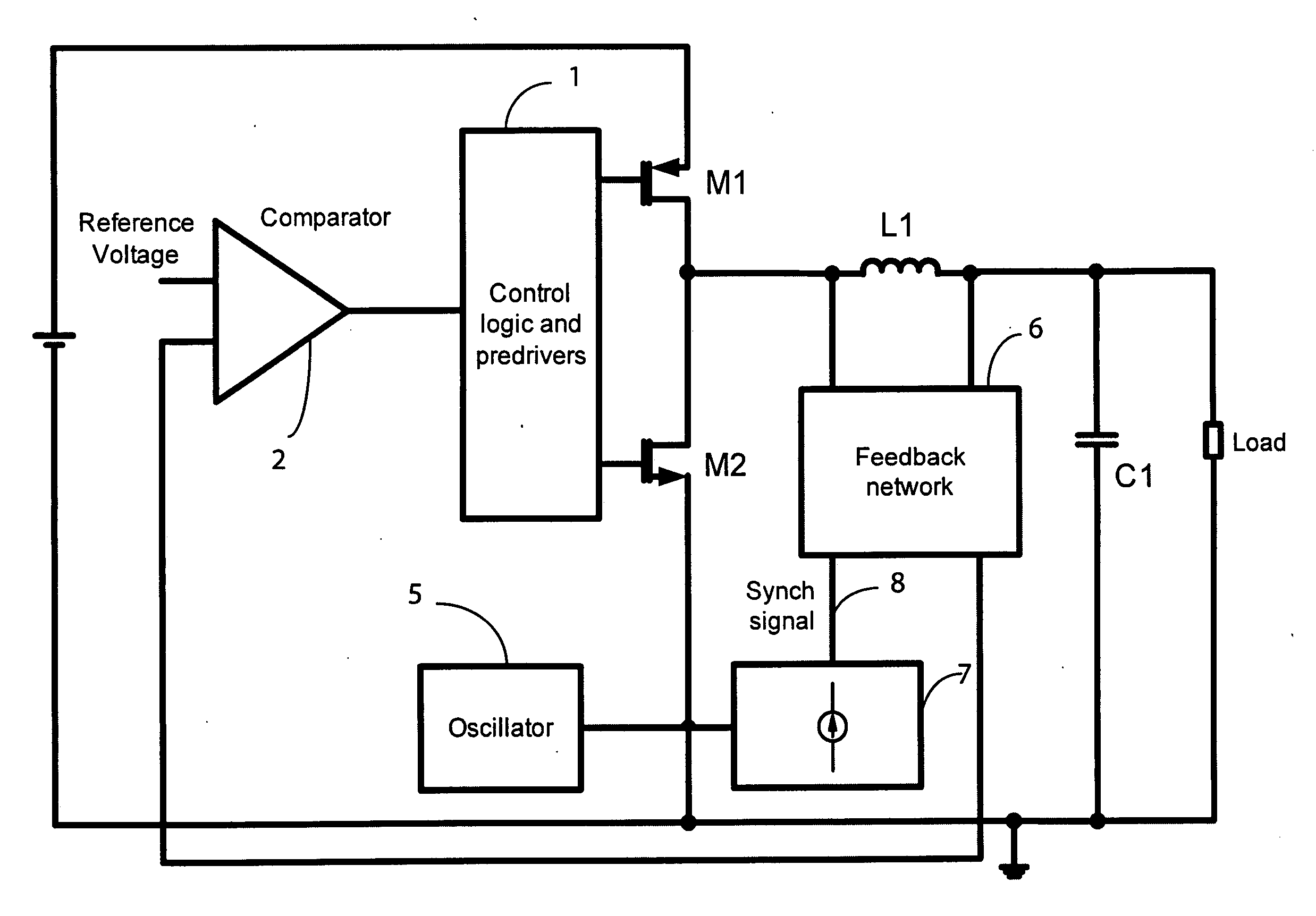
[0061]FIG. 2 shows a general implementation of the present invention where the oscillator 5 generates a clock signal at the desired frequency that is fed to the block 7. The block 7 generates the synchronization signal operating at the same frequency of the clock generated by the oscillator 5 with very small duty cycle. The synchronization signal 8 is fed into a node of the feedback network 6.
[0062]The disturbance signal could be introduced in many nodes of the hysteretic loop including in appropriate nodes of the comparator 2 of FIG. 2, however the injection of the signal in the feedback network 6 appears to be quite convenient not to alter the DC regulation point of the output voltage. Furthermore typically high and low impedance nodes are present in the feedback network giving flexibility to the types and amplitudes of injected signals and to the desired frequency to be synchronized.
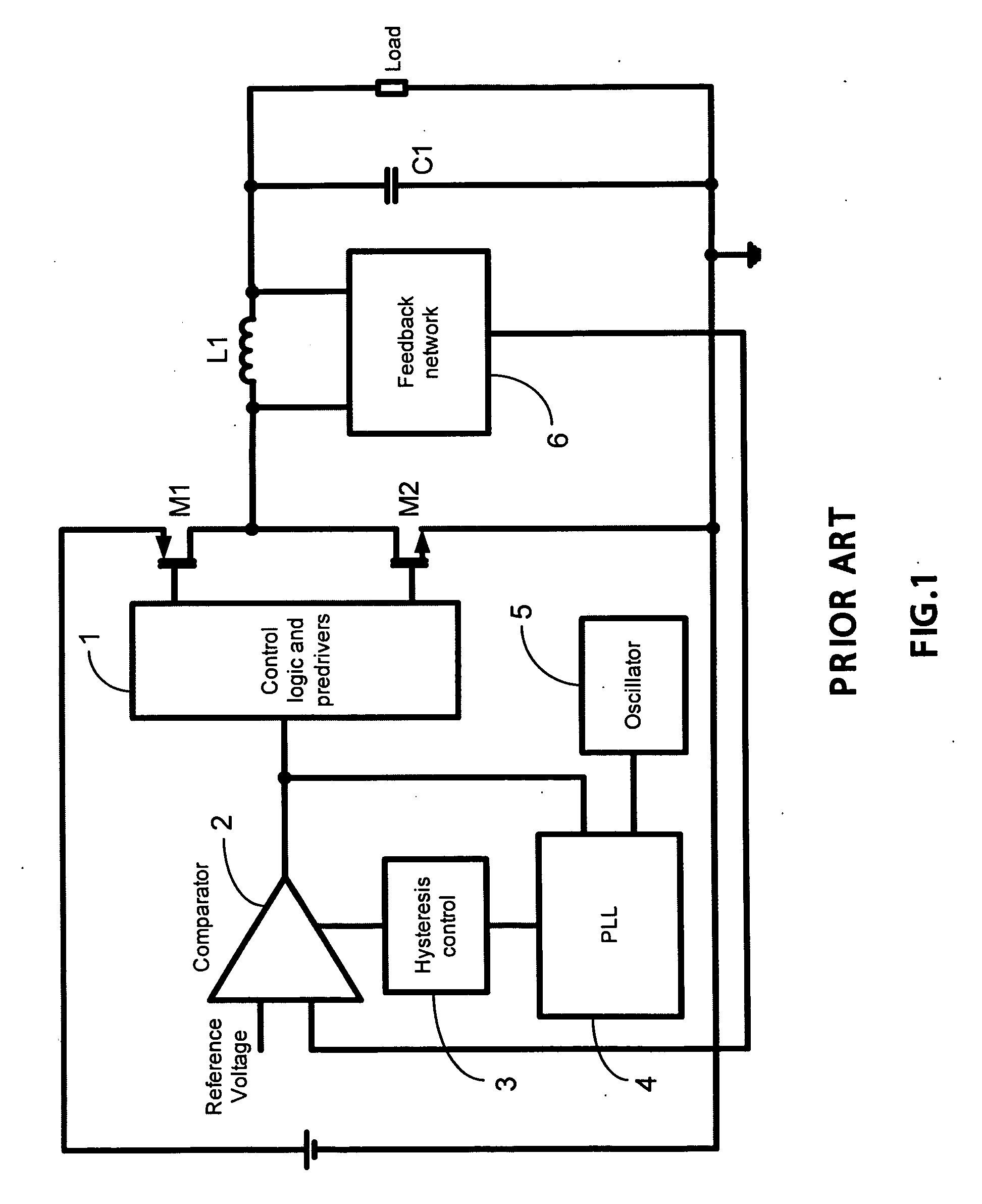
[0063]This is an open loop approach with respect operation of the prior art, as depicted i...
PUM
 Abstract
Description
Claims
Application Information