Valve unit and temperature control apparatus

Pending Publication Date: 2022-03-10
SHINWA CONTROLS
View PDF0 Cites 0 Cited by
  • Summary
  • Abstract
  • Description
  • Claims
  • Application Information

AI Technical Summary

Benefits of technology

The present invention provides a valve unit that can quickly switch fluids of different temperatures and supply a fluid while suppressing temperature fluctuations. This results in a temperature control apparatus that can control the temperature of an object from high to low and vice versa in a wide range. This is useful in applications such as plasma etching, where rapid and precise temperature control improves throughput.

Problems solved by technology

However, a variable valve used in the temperature control system of Patent Document 1 (JP2013-105359A), which is a solenoid proportional valve which regulates an opening degree depending on a value of a current to be applied, is not always capable to quickly switch opening and closing.
Thus, when the solenoid proportional valve is used in controlling a liquid at a large flow rate, leakage is likely to occur especially when the valve is in a close state.
Thus, in the system of Patent Document 1, when a liquid flow rate is large, a temperature may not be precisely controlled because a fluid supplied from a variable valve of a high-temperature channel, for example, can be mixed with a fluid leaked from another variable valve.

Method used


Image

  • Valve unit and temperature control apparatus
  • Valve unit and temperature control apparatus
  • Valve unit and temperature control apparatus

Examples


first embodiment

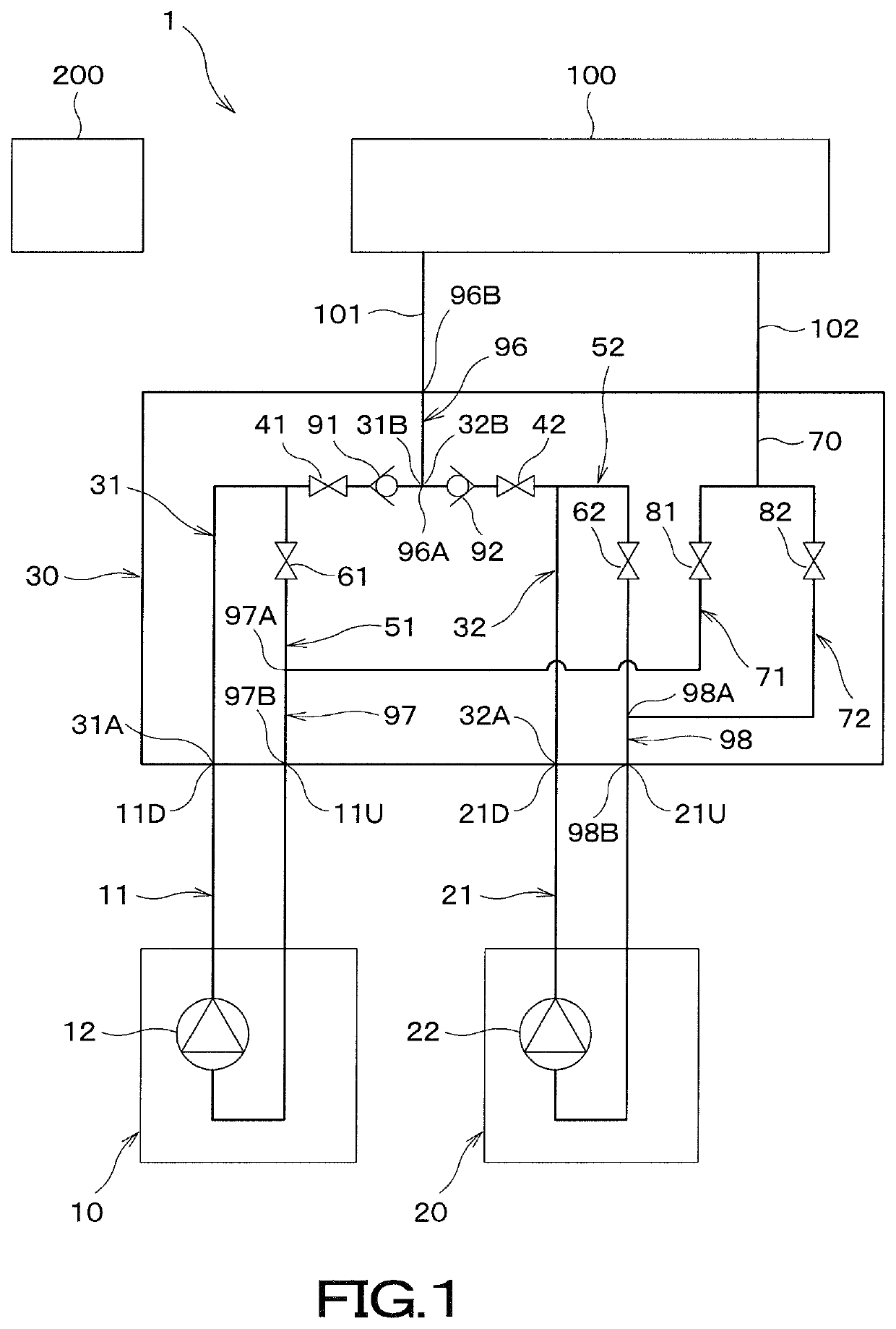
[0046]FIG. 1 is a schematic view of a temperature control apparatus 1 comprising a valve unit 30 according to a first embodiment. The temperature control apparatus 1 is used for controlling, for example, a temperature of a substrate holding unit of a plasma processing apparatus which removes a resist applied to a substrate during manufacture of semiconductors by plasma etching, so as to control a temperature of a substrate held on the substrate holding unit to a desired temperature. However, the use of the present invention is not particularly limited.

[0047]A schematic structure of the temperature control apparatus 1 according to this embodiment is described first.

[0048]As shown in FIG. 1, the temperature control apparatus 1 according to this embodiment comprises: a first temperature control unit 10 having a first fluid channel 11 that allows a first fluid whose temperature has been controlled to a first temperature to flow therethrough; a second temperature control unit 20 having a...

second embodiment

[0103]Next, a temperature control apparatus comprising a valve unit 130 according to a second embodiment of the present invention is described with reference to FIGS. 5 to 7. FIG. 5 is a schematic view of the temperature control apparatus comprising the valve unit 130 according to the second embodiment. Constituent elements in this embodiment which are similar to those of the first embodiment may be designated by the same reference numeral, and description thereof may be omitted.

[0104]As shown in FIG. 5, the valve unit 130 according to this embodiment comprises a first supply channel 31, a second supply channel 32, a supply-side channel switching three-way valve 131, a first branch channel 51, a first branch-side solenoid switching valve 61, a second branch channel 52, a second branch-side solenoid switching valve 62, a circulation-side channel switching three-way valve 132, a first circulation channel 71, and a second circulation channel 72.

[0105]The first supply channel 31 has a ...

third embodiment

[0120]Next, a valve unit 230 according to a third embodiment of the present invention is described with reference to FIG. 8. Constituent elements in this embodiment which are similar to those of the first and second embodiments may be designated by the same reference numeral, and description thereof may be omitted.

[0121]As shown in FIG. 8, the valve unit 230 according to this embodiment comprises a first supply channel 31, a first supply-side solenoid switching valve 41, a first branch channel 51, a second supply channel 32, a second supply-side solenoid switching valve 42, a second branch channel 52, a reception channel 70, a first circulation channel 71, a second circulation channel 72, a first circulation-side channel switching three-way valve 141, and a second circulation-side channel switching three-way valve 142.

[0122]The first supply channel 31 is configured to allow a first fluid flowing into a first inlet opening 31A to flow therethrough and to flow out from a first outlet ...


PUM


Abstract

A valve unit includes a first solenoid valve for a first fluid in a first channel; a first branch channel branched from the first channel on the upstream side of the first supply-side solenoid valve; a first branch-side switching valve for the first fluid in the first branch channel; a second solenoid valve for a second fluid in a second channel; a second branch channel branched from the second channel on the upstream side of the second solenoid valve; a solenoid switching valve for the second fluid in the second branch channel; a reception channel to receive a fluid from a first outlet opening or a second outlet opening to flow through a predetermined area and returns; first and second circulation channels bifurcated from the reception channel; a first circulation-side solenoid valve for the first circulation channel; and a second circulation-side solenoid valve for the second circulation channel.

Description

TECHNICAL FIELD[0001]The present invention relates to a valve unit that switches a fluid flow by a plurality of valves, and a temperature control apparatus including the valve unit.BACKGROUND ART[0002]A plasma processing apparatus has been conventionally known, which removes a resist or the like applied to a substrate during manufacture of semiconductors by plasma etching. The plasma processing apparatus comprises a substrate holding unit that holds a substrate, and a high-frequency power source that applies a high-frequency power to generate a plasma. Such a plasma processing apparatus is typically provided with an apparatus that controls a temperature of the substrate holding unit. A substrate on the substrate holding unit is regulated to a desired temperature by the apparatus.[0003]As an apparatus for controlling a temperature of a member such as the aforementioned substrate holding unit, JP2013-105359A discloses a temperature control system that joins a liquid which has been reg...

Claims


Application Information

Patent Timeline
IPC IPC(8): G05D7/06
CPCG05D7/0652F16K31/06G05D23/1393F16K31/408G05D7/06G05D23/1902
Inventor ONO, SHIGEHIKOICHIYAMA, RYOJI
Owner SHINWA CONTROLS
Why Eureka
Try Eureka