Hole pattern for gas turbine combustor

a gas turbine engine and combustor technology, applied in the direction of machines/engines, mechanical equipment, lighting and heating apparatus, etc., can solve the problems of excessive fuel introduction of injectors and attendant rise in the temperature of combustion flames

Active Publication Date: 2009-12-17
RTX CORP
View PDF14 Cites 40 Cited by
  • Summary
  • Abstract
  • Description
  • Claims
  • Application Information

AI Technical Summary

Benefits of technology

[0010]In one example, the intermediate air holes are large...

Problems solved by technology

Concurrently, the fuel injectors introduce a stoichiometrically excessive quantity of fuel into the rich burn zone.
Initially, the fuel-air ratio of the combustion products changes from fuel rich to stoichiometric, causing an at...

Method used


Image

  • Hole pattern for gas turbine combustor
  • Hole pattern for gas turbine combustor
  • Hole pattern for gas turbine combustor

Examples


Embodiment Construction

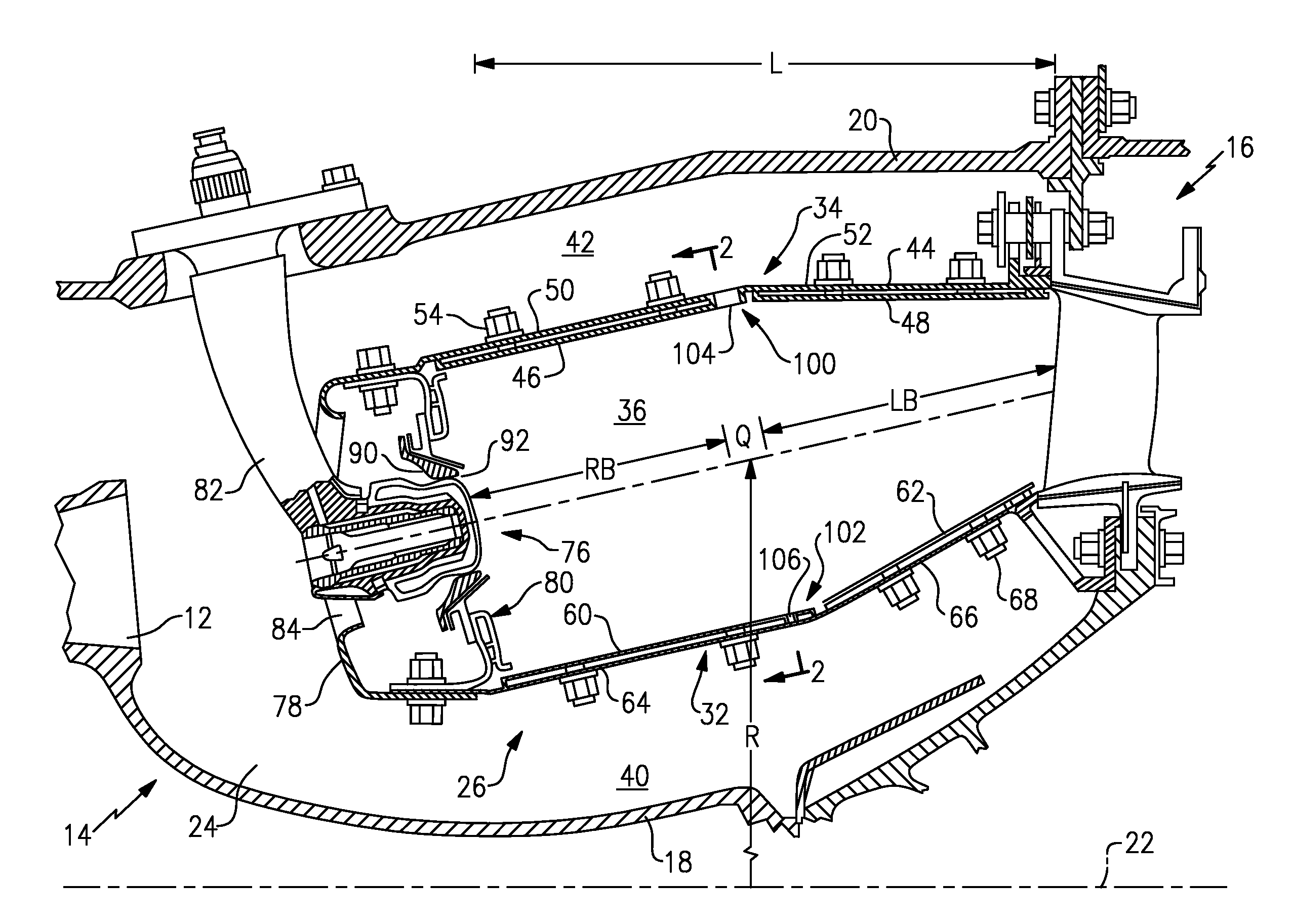
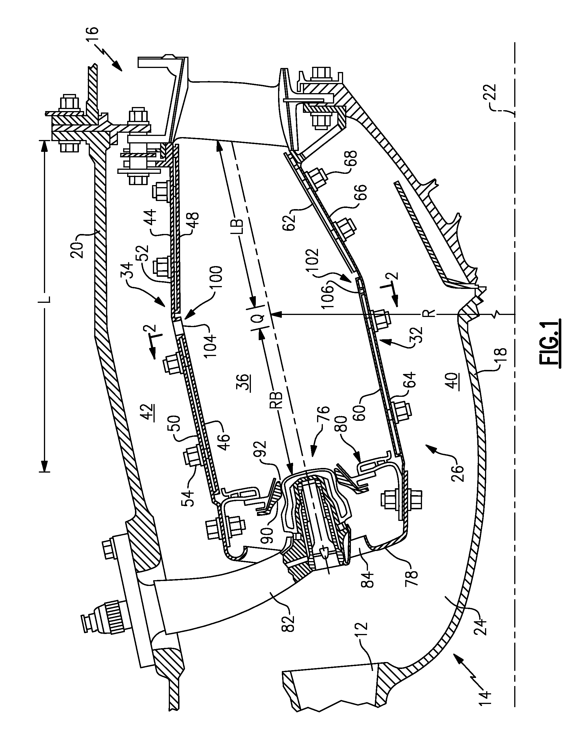
[0024]A gas turbine engine includes a compressor (not shown), a diffuser 12 (partially shown), a combustor module 14, and a turbine module 16 (partially shown). The combustor module 14 comprises a radially inner case 18 and a radially outer case 20, concentric with the radially inner case 18. The radially inner 18 and outer 20 cases circumscribe an axially extending engine centerline 22 to define an annular pressure vessel 24. The combustor module 14 also includes a combustor 26 residing within the annular pressure vessel 24. The combustor 26 includes a liner assembly comprising a radially inner liner 32 and a radially outer liner 34 that circumscribes the radially inner liner 32 to define an annular combustion chamber 36. The inner 32 and outer 34 liners cooperate with the inner 18 and outer 20 cases to define respective inner 40 and outer 42 air plenums.

[0025]In the example shown, the outer liner 34 comprises a single piece outer support shell 44 connected to the outer case 20, an...


PUM


Abstract

A combustor for a turbine engine includes an outer liner having a row of circumferentially distributed outer combustion air holes and an inner liner circumscribed by the outer liner and having a row of circumferentially distributed inner combustion air holes. The inner and outer liners each include at least a major air hole having a first hole size, an intermediate air hole having a second hole size, and a minor air hole having a third hole size. The first, second, and third hole sizes are all different from each other.

Description

BACKGROUND OF THE INVENTION[0001]This disclosure relates to a combustor for a gas turbine engine and, more particularly, to a hole pattern formed in inner and outer combustor liners.[0002]Gas turbine engines, such as those used to power modern commercial and military aircraft, include a compressor for pressurizing a supply of air, a combustor for burning a hydrocarbon fuel in the presence of the pressurized air, and a turbine for extracting energy from the resultant combustion gases. The combustor generally includes radially spaced apart inner and outer liners that define an annular combustion chamber therebetween. Arrays of circumferentially distributed combustion air holes penetrate multiple axial locations along each liner to radially admit the pressurized air into the combustion chamber. A plurality of circumferentially distributed fuel injectors project into the forward end of the combustion chamber to supply the fuel for mixing with the pressurized air.[0003]Combustion of the ...

Claims


Application Information

Patent Timeline
IPC IPC(8): F02C1/00
CPCF23R3/06F23R2900/03041Y02T50/675F23R2900/03044F23R2900/03042Y02T50/60
Inventor SHELLEY, JONATHAN K.CHEUNG, ALBERT K.BURD, STEVEN W.KOZOLA, STUART L.
Owner RTX CORP
Why Eureka
Try Eureka