A kinematic system for clamping semifinished products by means of pressing for sheet metal shaping panelling machines

a kinematic system and semi-finished product technology, applied in the direction of shafts, mechanical equipment, manufacturing tools, etc., can solve the problems of specific mechanical functions, unfavorable kinematic system work, and considerable reduction of the force delivered

Active Publication Date: 2009-12-17
FINN POWER
View PDF2 Cites 3 Cited by
  • Summary
  • Abstract
  • Description
  • Claims
  • Application Information

AI Technical Summary

Problems solved by technology

In hydraulic machines the traditional pentalateral type kinematic chain is used, however, to give the machine torsional rigidity and does not therefore have specific mechanical functions.
The kinematic designs for the control of the punch/presser in machines; of this type present the following limitation:if the machine is used with auxiliary tools positioned between the punch/presser and counter-punch or counter-blade (and in any other similar situation), the kinematic system works in unfavourable conditions, in which the pressing forces delivered are considerably reduced and insufficient (around_of the maximum force necessary) to guarantee the stability of all the sheet metal t

Method used


Image

  • A kinematic system for clamping semifinished products by means of pressing for sheet metal shaping panelling machines
  • A kinematic system for clamping semifinished products by means of pressing for sheet metal shaping panelling machines
  • A kinematic system for clamping semifinished products by means of pressing for sheet metal shaping panelling machines

Examples


Embodiment Construction

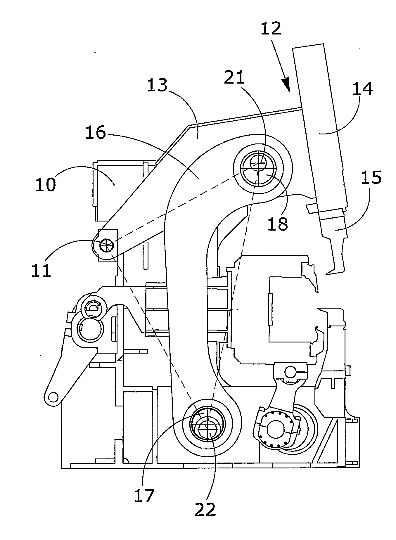
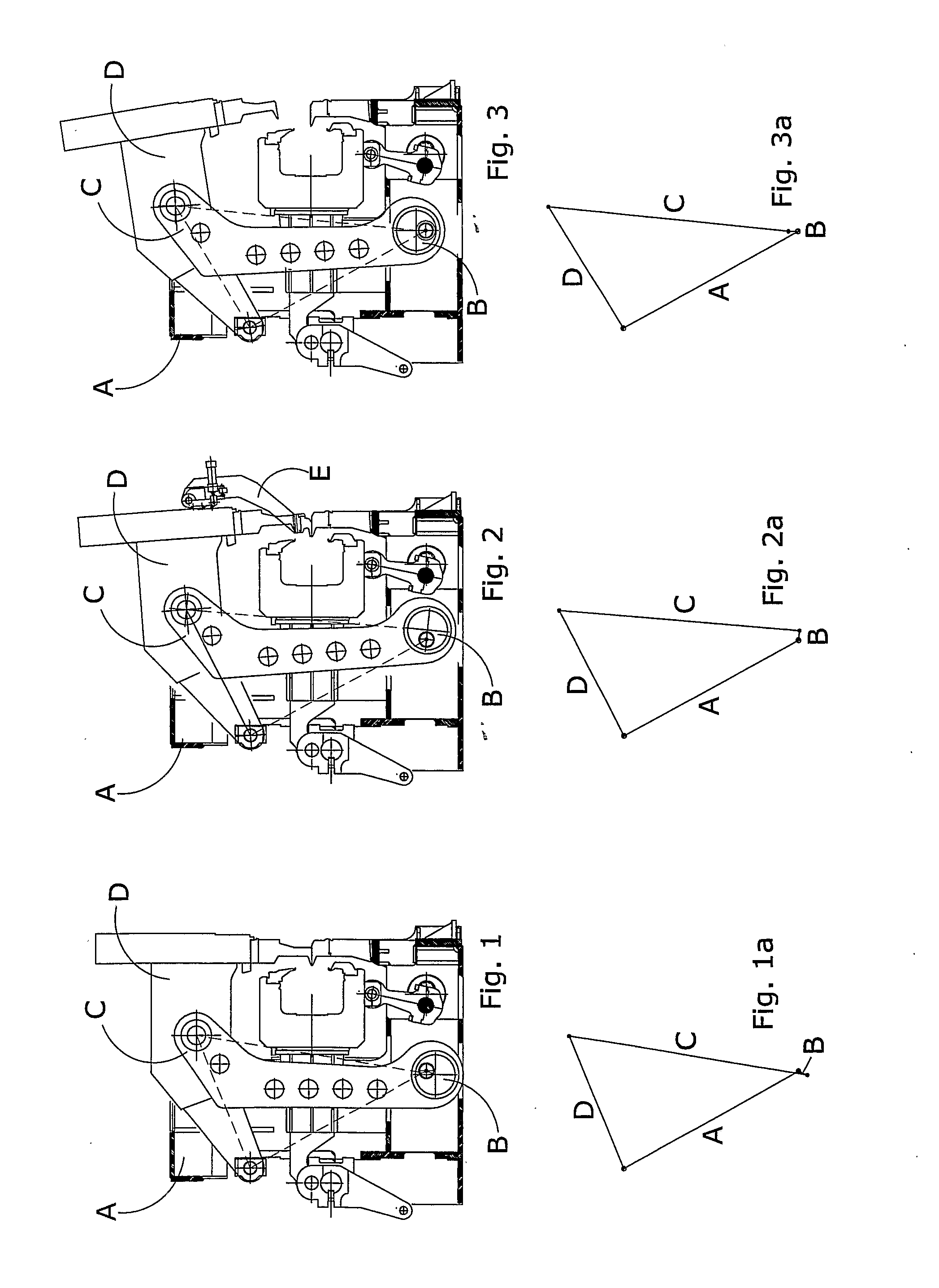
[0043]This invention proposes to provide a kinematic system for driving the pressing units of panelling machines that is able to eliminate or reduce the drawbacks described above, summarised in a reduced pressing force available when using auxiliary tools or when the pieces to be machines are particularly long or thick.

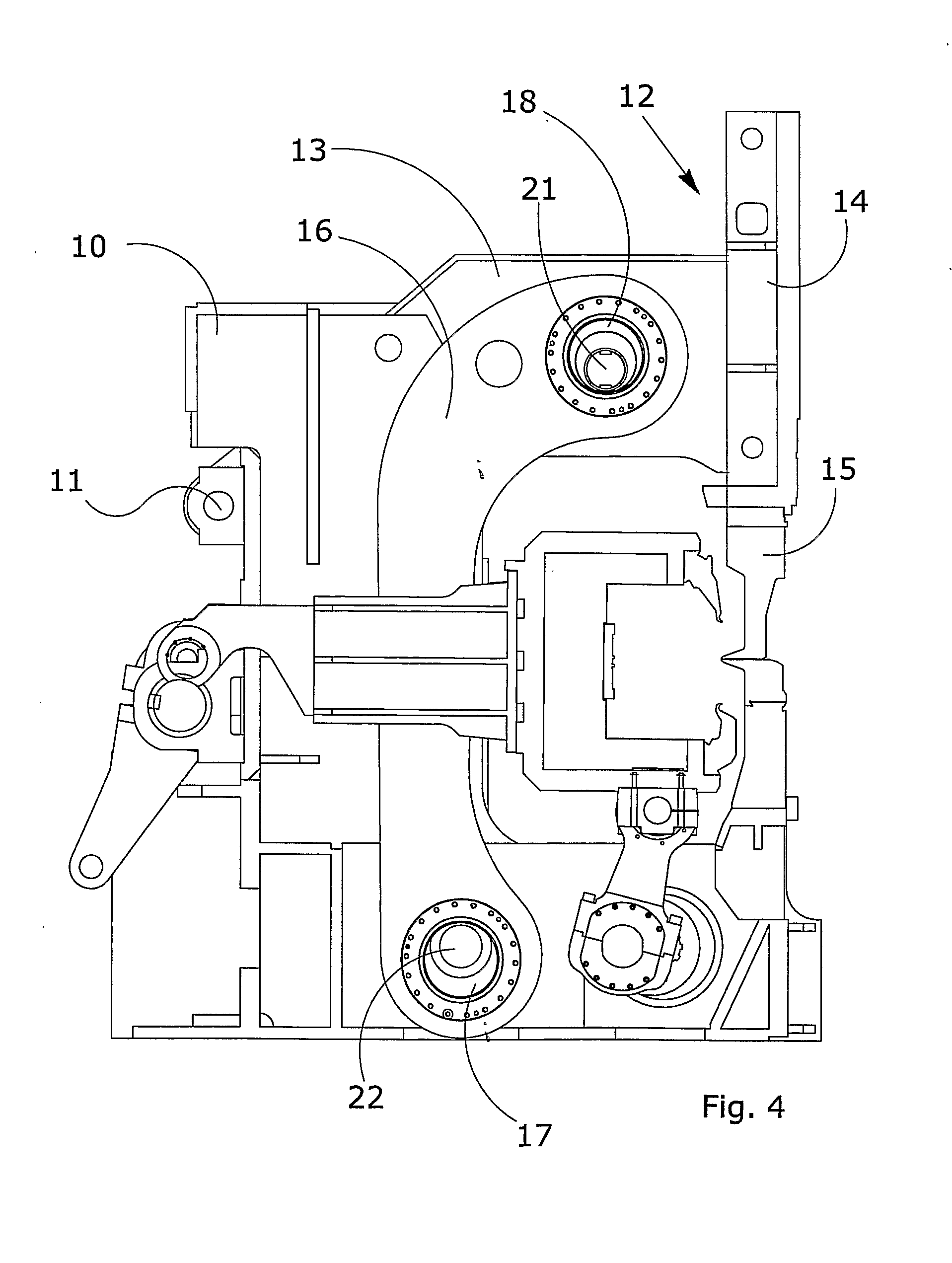
[0044]The invention proposes first of all to provide a kinematic system for driving the working units of a new design of panelling machine, which foresees the use of servomotors and epicycloidal or spheroidal reduction gears, that is to say motors with a high torque output (torque motors or similar) instead of traditional hydraulic actuators, for the movement of the pressing unit.

[0045]The servomotors and reduction gears in fact make it possible to achieve much higher performances than those of a hydraulic system, above all in the clamped rotor functioning typical of pressing operations.

[0046]This electrical control is made possible by a kinematic system for driving t...


PUM

PropertyMeasurementUnit
Angleaaaaaaaaaa
Degree of freedomaaaaaaaaaa

Abstract

A kinematic system of movement for the clamping/pressing unit of a semifinished piece, that is to say of sheet metal or the like, of panelling machines, the kinematic system comprising a frame on which a presser unit is hinged to a pin and which is free to make angular movements around the pin, the presser unit consisting of elements v fixed to a head supporting the upper presser tool, the presser unit being moved angularly by at least one connecting rod driven by a first lower crank, in which the presser unit is driven by a second upper crank, the first and second crank defining an articulated mechanism, for driving the punch-presser unit, with two degrees of freedom in sequence that can be activated independently or simultaneously.

Description

TECHNICAL FIELD[0001]This invention concerns a kinematic movement system for the clamping / pressing unit of semifinished products, that is to say of sheet metal, of new generation panelling machines, that is to say automatic machines for bending and shaping sheet metal.[0002]This kinematic system, suitable for electrical control and designed specifically for this, consists of a particular kinematic chain of the pressing unit, the unit which clamps the sheet metal during bending and which, unlike currently produced units, overcomes their main limitations.[0003]The system according to the invention can be applied to a panelling machine electrically controlled by means of motors which rotate the sheet metal clamping unit, often called a punch or presser unit.[0004]This system makes it possible to limit the working torque necessary to guarantee clamping of the sheet metal being pressed to within acceptable and limited values, even if additional auxiliary tools are used positioned between...

Claims


Application Information

Patent Timeline
IPC IPC(8): B21D5/04
CPCY10T74/2173B21D5/04B21D5/045
Inventor PATUZZI, LUIGI
Owner FINN POWER
Why Eureka
Try Eureka